
Polariton-Stabilized Solid-State Spin Clock

a solid-state spin clock and polariton technology, applied in the direction of preselected time interval producing apparatus, automatic control of pulses, instruments, etc., can solve the problems of thermal noise, limit the achievable fractional frequency deviation of a quantum-stabilized oscillator at long integration times, etc., to achieve better than millihertz stability, realistically achievable stabilization, and reduce oscillator temperature dependence

Active Publication Date: 2022-06-23
UNITED STATES OF AMERICA THE AS REPRESENTED BY THE SEC OF THE ARMY +1
View PDF2 Cites 0 Cited by
  • Summary
  • Abstract
  • Description
  • Claims
  • Application Information

AI Technical Summary

Benefits of technology

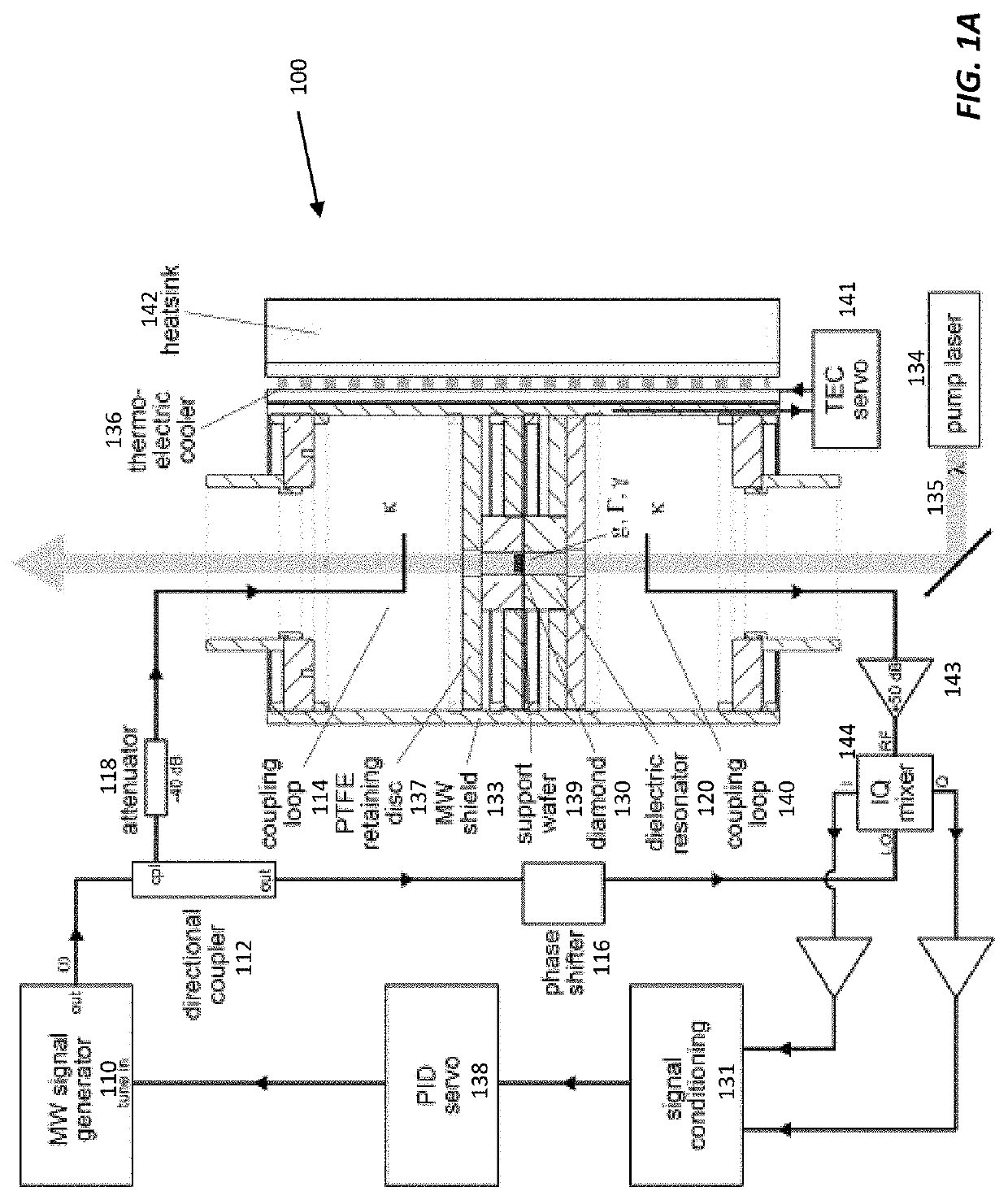
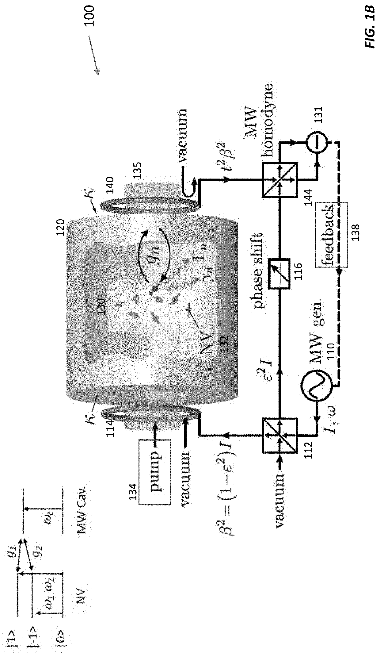
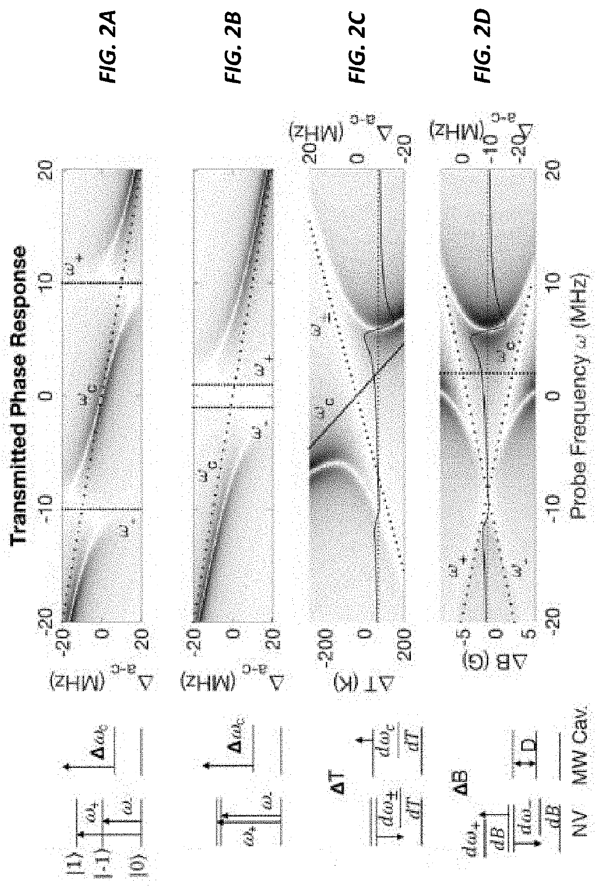
The patent addresses the problem of temperature stability in NV-diamond clocks and proposes a solution using a hybrid timekeeping device called a polaritonic system. This system involves coupling defect center spins with microwave cavity photons in a way that removes the first-order thermal response and results in better-than-millihertz stability. This stability of realistic spin-photon coupling strengths allows for a new class of solid-state, chip-integrated spin-based clocks with applications from positioning, navigation, and timing to instrumentation and telecommunications. The use of solid-state quantum defects trapped within a crystal lattice, which are stable in room-temperature environmental conditions, makes this approach ideal for chip-based implementations. The polariton-stabilized solid-state spin clock produces spin-microwave polariton eigenstates with a modified thermal and magnetic response that suppresses frequency fluctuations, resulting in millihertz stability for achievable coupling strengths. Overall, this patent proposes a path for improving the accuracy of clocks in challenging environments, making them more reliable and useful for a wide range of applications.

Problems solved by technology

Thermal noise, however, limits the achievable fractional frequency deviation of a quantum-stabilized oscillator at long integration times. The spin-spin interactions of the NV centers vary with temperature at a rate of about −80 kHz / K near room temperature.

Method used


Image

  • Polariton-Stabilized Solid-State Spin Clock
  • Polariton-Stabilized Solid-State Spin Clock
  • Polariton-Stabilized Solid-State Spin Clock

Examples


Embodiment Construction

[0027]A polariton-stabilized solid-state spin clock uses controlled coupling to suppress the thermal shifts of both the cavity and spin system, resulting in a stability improvement of five orders of magnitude for achievable thermal noise conditions while maintaining magnetic in-sensitivity. Combined with the large SNR of bulk NV sensors, this results in fractional frequency deviations that exceed current chip-scale atomic clocks and mechanical oscillators. A polariton-stabilized solid-state spin clock does not need precision optical elements. It can operate at ambient temperature and pressure and offers significant advantages in size, weight, and power over other clocks with similar performance. With CMOS integration and miniaturization of diamond, a polariton-stabilized solid-state spin clock enables a range of new applications using atomic-like timekeeping in a solid-state device.

[0028]Polaritonic stabilization is extensible to a variety of solid-state systems. Emitters in silicon...


PUM


Abstract

An ensemble of spin defect centers or other atom-like quantum systems in a solid-state host can be used as a compact alternative for an atomic clock thanks to an architecture that overcomes magnetic and temperature-induced systematics. A polariton-stabilized solid-state spin clock hybridizes a microwave resonator with a magnetic-field-insensitive spin transition within the ground state of a spin defect center (e.g., a nitrogen vacancy center in diamond). Detailed numerical and analytical modeling of this polariton-stabilized solid-state spin clock indicates a potential fractional frequency instability below 10-13 over a 1-second measurement time, assuming present-day experimental parameters. This stability is a significant improvement over the state-of-the-art in miniaturized atomic vapor clocks.

Description

CROSS-REFERENCE TO RELATED APPLICATION(S)[0001]This application claims the priority benefit, under 35 U.S.C. 119(e), of U.S. Application No. 63 / 127,564, filed on Dec. 18, 2020, which is incorporated herein by reference in its entirety.GOVERNMENT SUPPORT[0002]This invention was made with Government support under Grant No. W911NF-18-1-0432 awarded by the Army Research Office (ARO). The Government has certain rights in the invention.BACKGROUND[0003]Timekeeping is ubiquitous in the modern day, with clocks found in nearly all electronic devices and underpinning critical global infrastructure such as telecom networks and global navigation satellite systems. Clocks span the range from inexpensive, relatively imprecise voltage-controlled oscillators, through stabilized quartz oscillators, and finally to atomic frequency standards that set the state-of-the-art in accuracy. A longstanding goal is to bring the performance of atomic systems to the level of electronic circuits, for example, as c...

Claims


Application Information

Patent Timeline
Patent Type & Authority Applications(United States)
IPC IPC(8): G04F5/14H03L7/26
CPCG04F5/14H03L7/26G04F5/145
Inventor TRUSHEIM, MATTHEW EDWINJACOBS, KURTHOFFMAN, JONATHANFAHEY, DONALDENGLUND, DIRK ROBERT
Owner UNITED STATES OF AMERICA THE AS REPRESENTED BY THE SEC OF THE ARMY
Learn More