
A method for manufacturing a steel ingot

a manufacturing method and steel ingot technology, applied in the field of steel ingot manufacturing, can solve the problems of severe re-oxidation, unsuitable industrial steel production, and the described set-up is also unsuitable, so as to facilitate the formation of co-bubbles, improve the mechanical properties of the solidified ingot and products, and reduce the oxygen level in the steel

Pending Publication Date: 2022-06-16
OVAKO SWEDEN AB
View PDF2 Cites 0 Cited by
  • Summary
  • Abstract
  • Description
  • Claims
  • Application Information

AI Technical Summary

Benefits of technology

The present disclosure is a method for removing impurities from steel melt using a ceramic lining and a strong carbon effect at low pressures. The method saves money by not requiring costly conventional steel making steps prior to casting. By melting steel raw material in an electric arc furnace, treating it in a converter, and adjusting steel composition in the ladle, the method reduces production costs. The method also achieves efficient cleaning of the steel during solidification, resulting in a low content of oxides which improves mechanical properties of the solidified ingot and products produced therefrom. Additionally, the method uses an electromagnetic stirrer for effective stirring of the steel melt, reducing oxygen levels and forming CO-bubbles. The content of oxides in the solidified ingot is controlled to be below a predetermined threshold level, resulting in improved mechanical properties of the solidified ingot and products produced therefrom.

Problems solved by technology

Top filling, which was more commonly used 30 years ago, showed severe re-oxidation because of the exposure of the steel beam to air during teeming.
Both the ceramics and the mold powder has a great tendency for re-oxidizing the steel due to the fact that they consists of less stable oxides and will be reduced by the steel.
The described set-up is also not suitable for steel production on an industrial scale.

Method used


Image

  • A method for manufacturing a steel ingot
  • A method for manufacturing a steel ingot
  • A method for manufacturing a steel ingot

Examples


Embodiment Construction

[0045]The method for manufacturing a steel ingot according to the present disclosure will now be described more fully hereinafter. The method according to the present disclosure may however be embodied in many different forms and should not be construed as limited to the embodiments set forth herein. Rather, these embodiments are provided by way of example so that this disclosure will be thorough and complete, and will fully convey the scope of the present disclosure to those persons skilled in the art. Same reference numbers refer to same elements throughout the description.

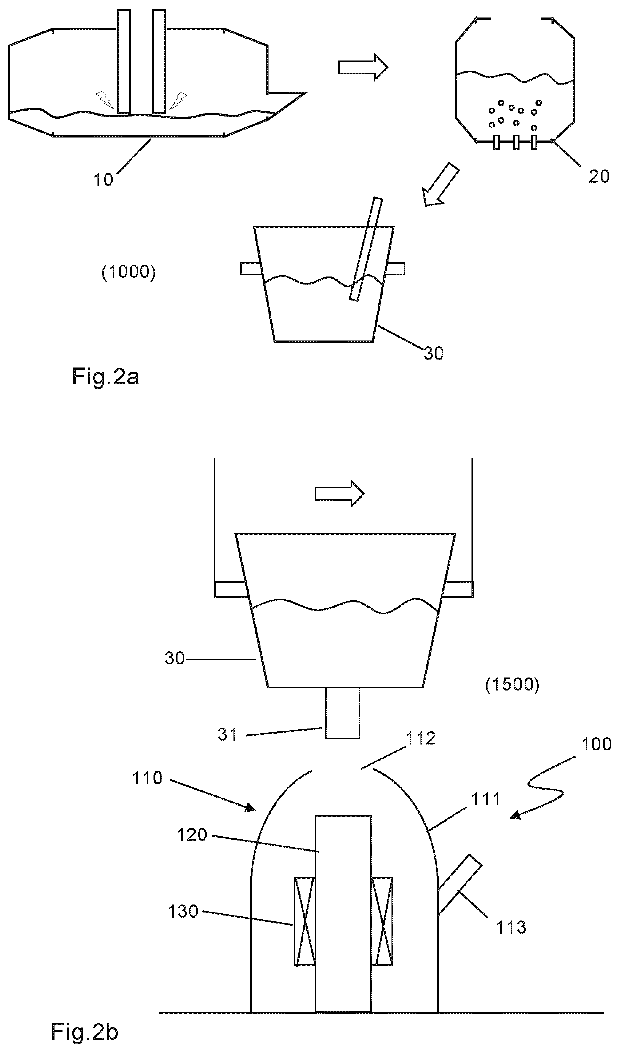
[0046]FIGS. 2a shows a first step 1000 of providing a steel melt. The steel melt may be produced by conventional steel making methods including melting steel raw material such as scrap metal in an electric arc furnace 10. The molten steel is poured into a ladle 20 for oxygen reduction and subsequently into a ladle 30 for refinement. The ladle 30 may provide a container for transporting the steel melt in the meth...


PUM

PropertyMeasurementUnit
Temperatureaaaaaaaaaa
Pressureaaaaaaaaaa
Pressureaaaaaaaaaa

Abstract

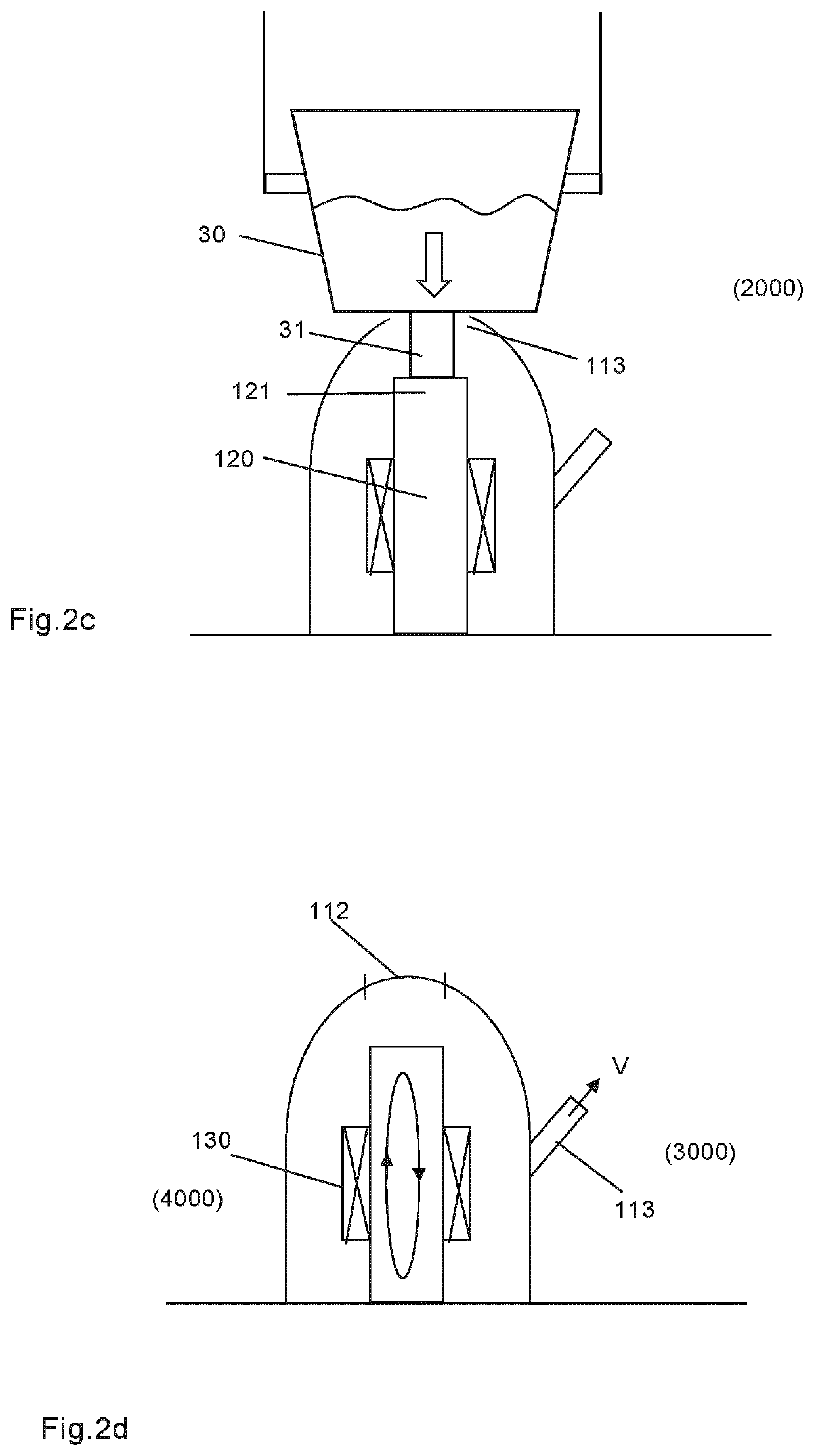
A method for manufacturing a steel ingot in a casting arrangement (100) comprising a vacuum vessel (110); an ingot mold (120) arranged within the vacuum vessel and a stirrer (130) arranged to stir liquid steel in the ingot mold, comprising: -providing (1000) a liquid steel melt; filling (2000) the ingot mold (100) with the liquid steel melt; applying (3000) a reduced pressure within the vacuum vessel (110); allowing the liquid steel melt to solidify into an ingot; allowing the liquid steel melt to solidify under stirring within the ingot mold at a reduced pressure during solidification of the steel melt; wherein, the liquid steel melt comprises a predetermined amount of carbon and; incidental impurity elements in the form of oxides, wherein during stirring the oxides are reduced by carbothermic reaction in which oxygen in the oxides and carbon in the steel melt form carbon-monoxide.

Description

TECHNICAL FIELD[0001]The present disclosure relates to a method for manufacturing a steel ingot in a casting arrangement.BACKGROUND ART[0002]In conventional steelmaking, molten metal from the smelting furnace is usually poured into a ladle, from which the metal then is poured into vessels for further production steps. Molten metal may be poured from the lip at the top of the ladle when the ladle is of small capacity. When the ladle is larger, the metal is poured through a refractory nozzle at the bottom of the ladle. The nozzle can be closed from inside the ladle by a refractory stopper. Devices without stoppers are also widely used. Here, the ladle's nozzle is closed from the outside by a refractory plate. The plate, which has an orifice, can be moved so that the orifice coincides with the nozzle, thus allowing the metal to flow out.[0003]In the ingot steel industry, molten steel is poured from a ladle into molds, The metal can be poured into the mold either from the top of the mol...

Claims


Application Information

Patent Timeline
IPC IPC(8): B22D7/00B22D18/06B22D27/02C22C38/18C22C38/04C22C38/02
CPCB22D7/00B22D18/06C22C38/02C22C38/18C22C38/04B22D27/02B22D27/15B22D27/04C21C7/0025C21C7/10C21C7/06
Inventor ANDERSSON, JAN-ERIKFAGERLUND, JOAKIM
Owner OVAKO SWEDEN AB
Learn More