
Carbon Nanotube, And Electrode And Secondary Battery Including Carbon Nanotube

a carbon nanotube and secondary battery technology, applied in the field of carbon nanotubes, electrodes and secondary batteries including carbon nanotubes, can solve the problems of insufficient effect of improving electrical conductivity, complex single layer structure, and increased manufacturing cost, and achieves low crystallinity, high flexibility, and high flexibility.

Pending Publication Date: 2022-05-05
LG ENERGY SOLUTION LTD
View PDF0 Cites 0 Cited by
  • Summary
  • Abstract
  • Description
  • Claims
  • Application Information

AI Technical Summary

Benefits of technology

The present invention concerns a carbon nanotube with a short growth unit and low crystallinity, which is highly flexible and can smoothly adhere to active material particles, reducing battery resistance. The carbon nanotube has specific surface areas ranging from 100 to 196 m2 / g, which minimizes side reactions with electrolyte solution and enables smooth dispersion in an electrode. The carbon nanotube is uniformly dispersed in an electrode slurry and has many defects on its surface, which improves the lifespan properties of the manufactured battery.

Problems solved by technology

However, even though it is advantageous to form a graphene as a single layer in order to improve conductivity, a process for manufacturing the same in the form of a single layer is very complicated, so that manufacturing cost is increased.
On the other hand, when a graphene has a thickness greater than or equal to a desired level, there is a problem in that the effect of improving electrical conductivity is insufficient.
In addition, even when a graphene having a thickness of a desired level of 10 nm or less is used as a conductive material, it is difficult to easily migrate in an electrolyte solution in an electrode due to the excessive surface contact of the graphene, so that the resistance of the electrode increases, resulting in the deterioration in the performance of a battery.
Meanwhile, a typical carbon nanotube corresponding to the linear conductive material has an excellent electrical conductivity, but has an excessively high crystallinity, and thus, has a low flexibility and is rigid.
Therefore, it is difficult for the carbon nanotube to be smoothly adhered along the surface of an active material particle, and the carbon nanotube is linearly arranged on a three-dimensional space randomly.
Accordingly, a point or an area of contact between the active material particle and the carbon nanotube is reduced, which makes it difficult to secure a conductive path, and there is a problem in that the resistance of a battery increases.
In addition, the typical carbon nanotube is not be smoothly dispersed in a slurry for forming an electrode, so that the resistance in the electrode is not uniform, and there is a problem in that the lifespan properties of a battery are deteriorated.
However, such a method does not change the physical properties of the carbon nanotube itself, and thus, has a limitation in solving the above-mentioned problems.

Method used


Image

  • Carbon Nanotube, And Electrode And Secondary Battery Including Carbon Nanotube
  • Carbon Nanotube, And Electrode And Secondary Battery Including Carbon Nanotube
  • Carbon Nanotube, And Electrode And Secondary Battery Including Carbon Nanotube

Examples


example 2

Carbon Nanotubes

[0096]Carbon nanotubes having an average diameter of 12 nm were prepared in the same manner as in Example 1 except that Commercial Scale Reactor (Capacity of internal reaction vessel: 4 m3) was used as a fluidized bed reactor and the inflow rate of the mixed gas was changed to 28,000 sccm.

experimental example 1

on Nanotube Structure

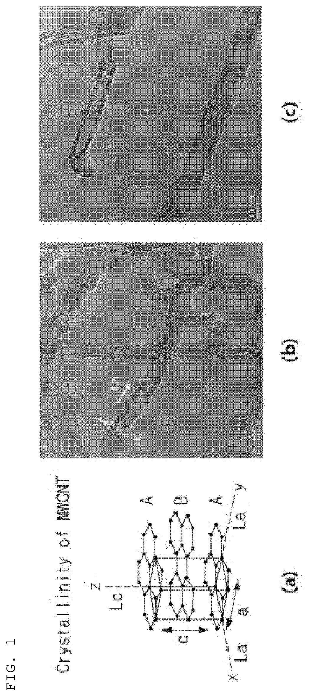
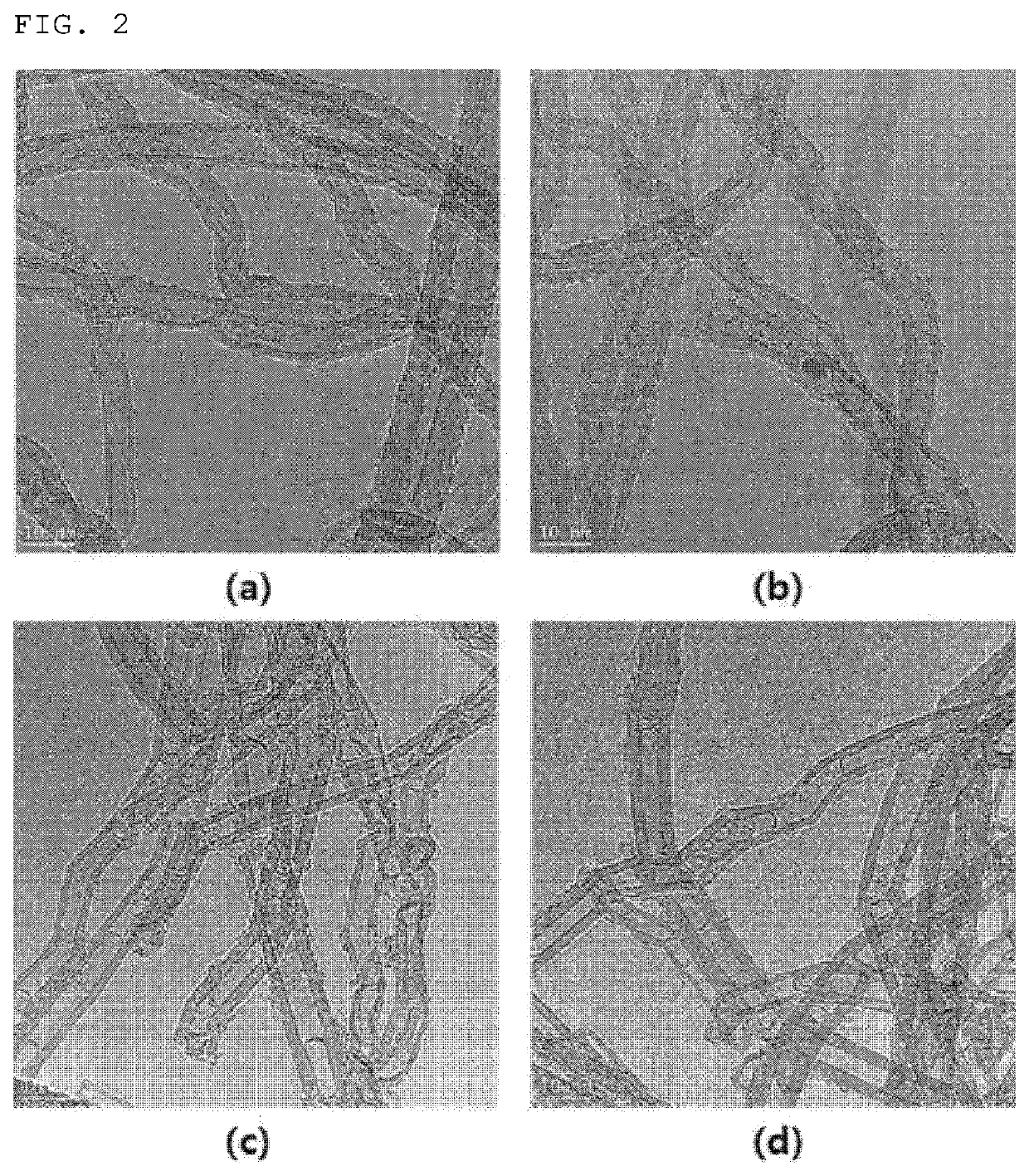
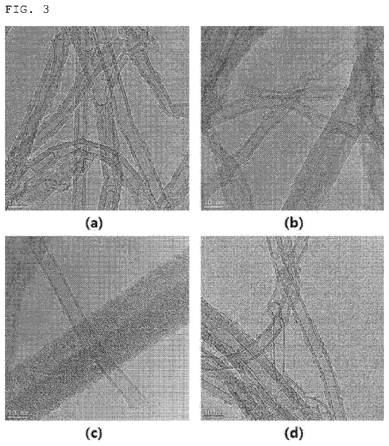
[0105]Each of the carbon nanotubes of Example 1 and Comparative Example 1 were observed through a TEM and the results are shown in FIG. 1. Specifically, FIG. 2 is TEM photographs of the carbon nanotubes of Example 1 before graphitization treatment at 2500° C. ((a) and (b) of FIG. 2) and TEM photographs of the carbon nanotubes of Example 1 after the graphitization treatment ((c) and (d) of FIG. 2). FIG. 3 is TEM photographs of the carbon nanotubes of Comparative Example 1 before graphitization treatment at 2500° C. ((a) and (b) of FIG. 3) and TEM photographs of the carbon nanotubes of Comparative Example 1 after the graphitization treatment ((c) and (d) of FIG. 3).

[0106]When comparing (a) and (b) of FIG. 2 and (a) and (b) of FIG. 3, it can be seen that the carbon nanotubes of Example 1 have more nodes (curved portions) and have a less linear shape than the carbon nanotubes of Comparative Example 1.

[0107]Also, referring not only to (a) and (b) of FIG. 2 and (a) an...

experimental example 2

arbon Nanotubes

[0108]The carbon nanotube powder resistance of the carbon nanotubes of each of Examples 1 and 2 and Comparative Examples 1 to 4 was measured in the following manner.

[0109]Using Loresta-GX (MCP-PD51) equipment, 0.5 g of carbon nanotube powder was filled in a sample holder and pressed to 400 kN, 800 kN, 1200 kN, 1600 kN, and 2000 kN to evaluate a powder resistance value (Ohm·cm) at 60 MPa.


PUM

PropertyMeasurementUnit
specific surface areaaaaaaaaaaa
diameteraaaaaaaaaa
thicknessaaaaaaaaaa

Abstract

The present invention relates to a carbon nanotube having an La(100) of less than 7.0 nm when measured by XRD and a specific surface area of 100 m2 / g to 196 m2 / g, and an electrode and a secondary battery including the carbon nanotube.

Description

CROSS-REFERENCE TO RELATED APPLICATIONS[0001]This application claims the benefit of Korean Patent Application Nos. 10-2019-0026479, filed on Mar. 7, 2019, and 10-2019-000027180, filed on Mar. 8, 2019, in the Korean Intellectual Property Office, the disclosures of which are incorporated herein in their entirety by reference.TECHNICAL FIELD[0002]The present invention relates to a carbon nanotube having an La(100) of less than 7.0 nm when measured by XRD and a specific surface area of 100 m2 / g to 196 m2 / g, and an electrode and a secondary battery including the carbon nanotube.BACKGROUND ART[0003]As technology development and demand for mobile devices have increased in recent years, the demand for secondary batteries as an energy source has been rapidly increased. Accordingly, various studies have been conducted on batteries which may meet various needs. In particular, research has been actively conducted on a lithium secondary battery having high energy density and excellent lifespan a...

Claims


Application Information

Patent Timeline
Patent Type & Authority Applications(United States)
IPC IPC(8): H01M4/583C01B32/162
CPCH01M4/583C01B32/162C01B2202/06C01B2202/32C01P2002/70C01B2202/36C01P2002/82C01B32/158C01B32/159H01M4/625H01M4/13H01M10/0525Y02E60/10H01M4/587H01M50/417C01B2202/22C01P2002/60B01J23/8472
Inventor KIM, TAE GONJUNG, WANG MOYOON, KWANG WOOSON, SEUNG YONGCHAE, BYUNG JOONPARK, SIN YOUNGSOHN, SE HUILEE, DAE JINLEE, BO RAMKIM, HAK YOONKIM, SEUL KIHWANG, JIN YOUNG
Owner LG ENERGY SOLUTION LTD
Learn More