
Fiber-reinforced composite part with increased vibration resistance

Pending Publication Date: 2022-03-10
SAFRAN
View PDF0 Cites 0 Cited by
  • Summary
  • Abstract
  • Description
  • Claims
  • Application Information

AI Technical Summary

Benefits of technology

This invention proposes a part for a turbomachine with a mechanism to reduce vibrations. This helps to create a more precise shape, especially for parts that need to be aerodynamic. It also helps to prevent the part from hitting a resonance point.

Problems solved by technology

However, during the operation of the turbomachine, the parts of said turbomachine may be subject to vibrations.
However, a part excited at one of its own modes risks becoming damaged and damaging neighboring components.
Thus the current situation does not make it possible to give the part its optimized shape.

Method used


Image

  • Fiber-reinforced composite part with increased vibration resistance
  • Fiber-reinforced composite part with increased vibration resistance
  • Fiber-reinforced composite part with increased vibration resistance

Examples


Embodiment Construction

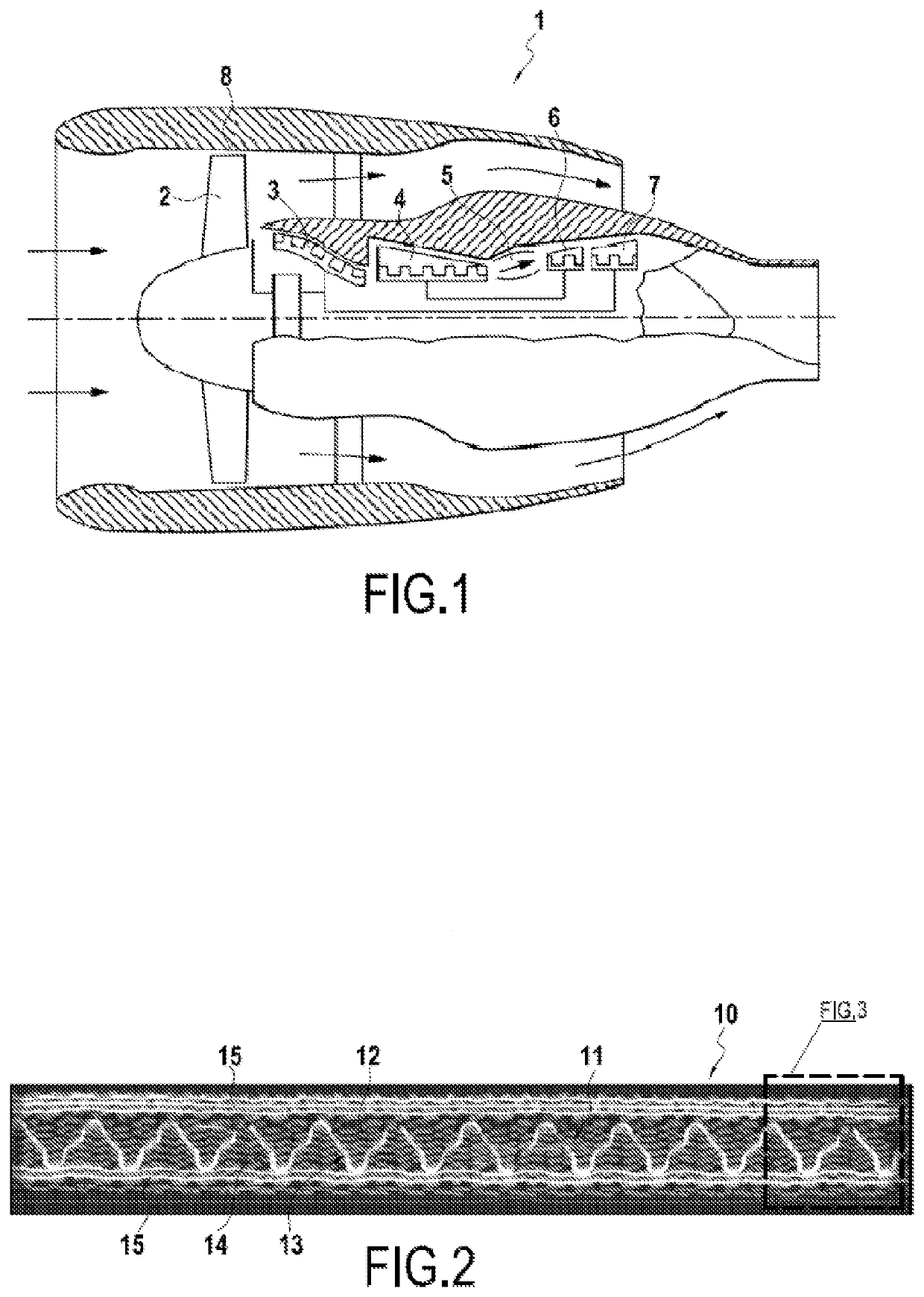
[0032]As illustrated in FIG. 1, along the direction of circulation of the air flow, a turbomachine 1 comprises a fan 2, a low-pressure compressor 3, a high-pressure compressor 4, a combustion chamber 5, a high-pressure turbine 6, and a low-pressure turbine 7.

[0033]In addition, the turbomachine 1 comprises different casings, such as for example a fan casing 8 which surrounds the fan 2, which surround different elements of said turbomachine 1.

[0034]Furthermore, the turbomachine 1 can be a turbomachine with a reduction gear, thus making it possible to uncouple the fan 2 and the low-pressure turbine 7, or else the fan 2 can be directly coupled to the low-pressure shaft which is rotationally driven by the low-pressure turbine 7.

[0035]The invention can be applicable for various parts of the turbomachine 1 which are subject to vibrations and which are thus liable to enter resonance, and particularly for blades of said turbomachine. Specifically, the blades of the turbomachine are elements ...


PUM

PropertyMeasurementUnit
Temperatureaaaaaaaaaa
Frequencyaaaaaaaaaa

Abstract

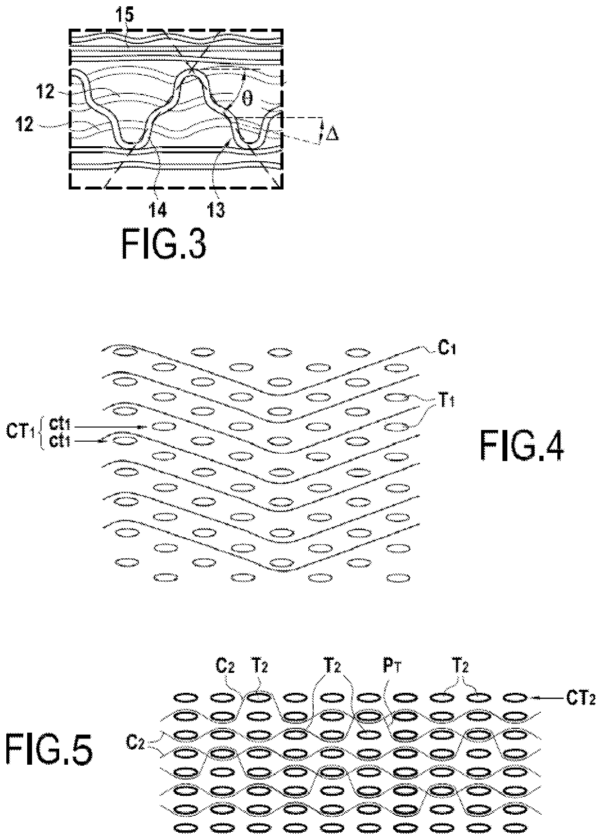
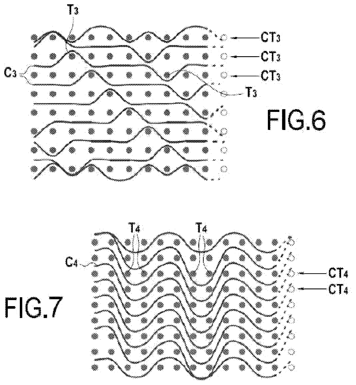
A part of a turbomachine made of composite material includes a fiber reinforcement having a three-dimensional weaving including a first set of yarns made of a first material, wherein the fiber reinforcement includes a vibration-damping element formed by a second set of yarns including a second material which is viscoelastic and which is different to the first material, the second set of yarns being woven with the first set of yarns.

Description

TECHNICAL FIELD[0001]This invention relates to the general field of turbomachines, and more particularly turbomachines for aircraft.PRIOR ART[0002]It is known to use turbomachine parts which are made of composite material with a fiber reinforcement made by three-dimensional weaving, particularly for fan blades.[0003]However, during the operation of the turbomachine, the parts of said turbomachine may be subject to vibrations. These vibrations can excite the parts in a natural mode of said parts. However, a part excited at one of its own modes risks becoming damaged and damaging neighboring components.[0004]Thus, in order to avoid a part being excited at one of its own modes, it is known to adapt the shape of said part. For example, fan blades have a shape that is adapted to minimize the excitation of said fan blades at their natural modes.[0005]However, an optimized shape of the part, i.e. a shape making it possible to improve the performance of the part, can be a shape for which a ...

Claims


Application Information

Patent Timeline
IPC IPC(8): F01D5/14B29C70/24D03D25/00
CPCF01D5/147B29C70/24B29L2031/082F05D2220/32F05D2240/301D03D25/005B29L2031/08F01D25/005F05D2300/6033F05D2300/6034F05D2300/224F05D2220/36F01D5/282D10B2505/02Y02T50/60B29B11/16F04D29/324
Inventor DAMBRINE, BRUNO JACQUES GÉRARDTRANQUART, BASTIENCOUPE, DOMINIQUE MARIE CHRISTIANCOLOT, MARC-ANTOINE
Owner SAFRAN
Learn More