
Multi-bit memory element with groove structure and method for manufacturing same

A multi-bit storage and structure technology, applied in semiconductor/solid-state device manufacturing, electrical components, information storage, etc., to achieve the effect of optimizing the shape

Inactive Publication Date: 2007-07-04
QIMONDA
View PDF0 Cites 0 Cited by
  • Summary
  • Abstract
  • Description
  • Claims
  • Application Information

AI Technical Summary

Problems solved by technology

The disadvantage of planar transistors is that the channel length of the transistor must be scaled with the feature size F (scalieren)
However, channels that are correspondingly shorter as devices are miniaturized have the problem that the channels are determined by high voltages that occur when programming or erasing cells

Method used


Image

  • Multi-bit memory element with groove structure and method for manufacturing same
  • Multi-bit memory element with groove structure and method for manufacturing same
  • Multi-bit memory element with groove structure and method for manufacturing same

Examples


Embodiment Construction

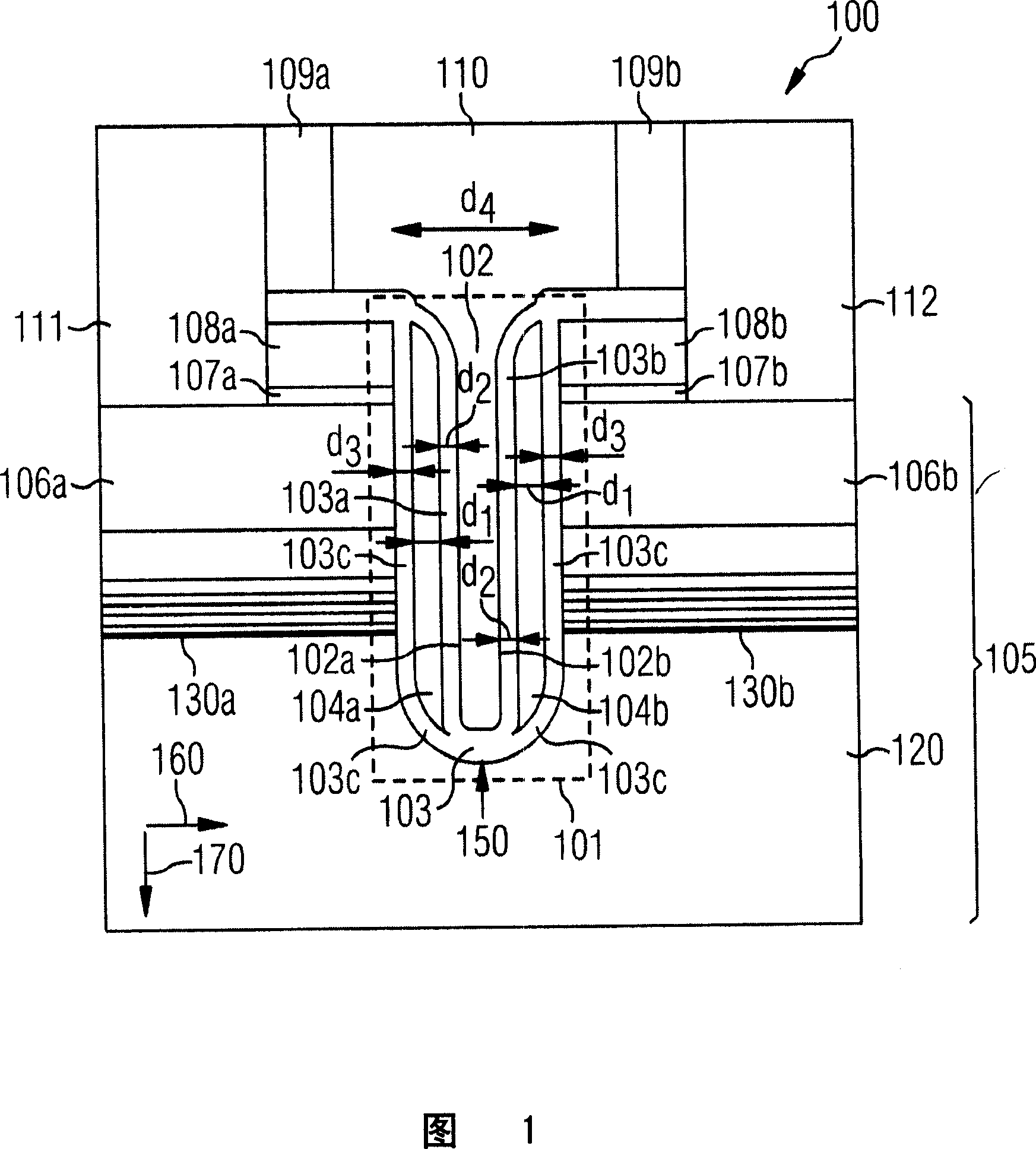
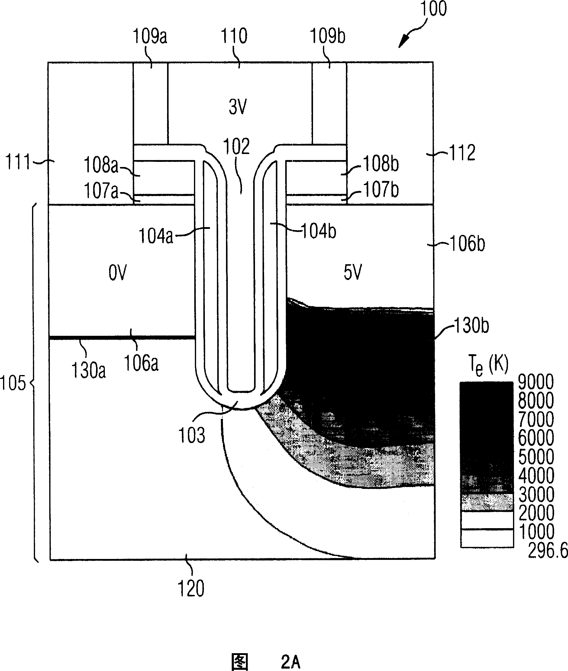
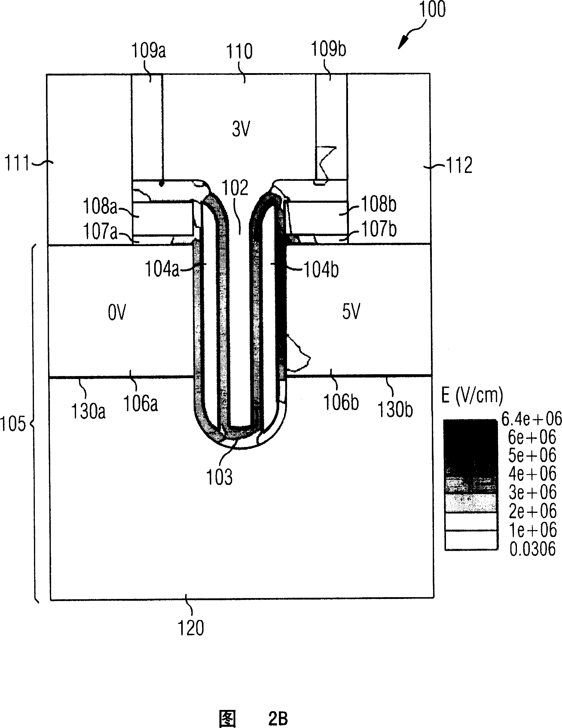
[0079] FIG. 1 shows a multi-bit memory element 100 having a trench structure 101 according to a first embodiment of the present invention. The trench structure 101 has a U-shaped structure with a curved lower section, wherein the deepest point of the trench structure 101 (apparently the curved section of the trench structure 101 or the apex of the "U") is indicated by the arrow 150 . The trench structure 101 has a conductive region 102 and an electrically insulating region 103 formed on the conductive region 102 . Furthermore, the trench structure 101 has a first floating gate region 104a and a second floating gate region 104b, which floating gate regions 104a, 104b are formed on or in the electrically insulating region 103, and the floating gate The pole regions 104 a , 104 b are electrically insulated from each other and from the conductive region 102 by the electrically insulating region 103 .

[0080]The first floating gate region 104a and the second floating gate region ...


PUM


Abstract

A multi-bit memory element comprise a trench structure comprising an electrically conductive region on which is an insulating region in or on which are at least two floating gate regions that are electrically isolated from one another and from the electrically conductive region.

Description

technical field [0001] The invention relates to a multi-bit storage element with a trench structure and a method for manufacturing a multi-bit storage element with a trench structure. Background technique [0002] The most important subfield of semiconductor technology is the development of memory elements or memory cells (Memory Cells), ie elements for storing data, usually in the form of binary information units, ie bits (binary bits). In this regard, writing (Writing) or programming (Programming) a memory cell should be understood as "writing", ie storing, data (eg, a bit) into the cell. In addition, reading (Read) or deleting (Erase) a storage unit should be understood as reading or deleting the content of the storage unit, that is, the stored information. In addition, the read / write process is also called a cycle (Cycle), and the time between the start of one read / write process and the start of another read / write process is called a cycle duration (Cycle Time). [000...

Claims


Application Information

Patent Timeline
IPC IPC(8): H01L27/115H01L29/788H01L29/423H01L21/8247H01L21/336H01L21/28
CPCH01L29/66825G11C16/0458H01L29/7887H01L21/28273H01L29/42336H01L29/40114
Inventor F·刘
Owner QIMONDA
Learn More