
Special oil-water separator

A technology of oil-water separation and oil-water separation device, which is applied in the direction of liquid separation, separation method, water treatment parameter control, etc. It can solve the problems of unbalanced air flow and achieve the effects of air pressure balance, reasonable position and optimized shape

Inactive Publication Date: 2015-05-20
SUZHOU MEISHENG ENVIRONMENTAL PROTECTION TECH
View PDF11 Cites 2 Cited by
  • Summary
  • Abstract
  • Description
  • Claims
  • Application Information

AI Technical Summary

Problems solved by technology

[0003] The technical problem mainly solved by the present invention is to provide a special oil-water separator, which has a reasonable design and a simple structure, and solves the discharge problem caused by the unbalanced air flow inside the box from the overall structure

Method used


Image

  • Special oil-water separator
  • Special oil-water separator
  • Special oil-water separator

Examples


Embodiment Construction

[0013] The preferred embodiments of the present invention will be described in detail below in conjunction with the accompanying drawings, so that the advantages and features of the present invention can be more easily understood by those skilled in the art, so as to define the protection scope of the present invention more clearly.

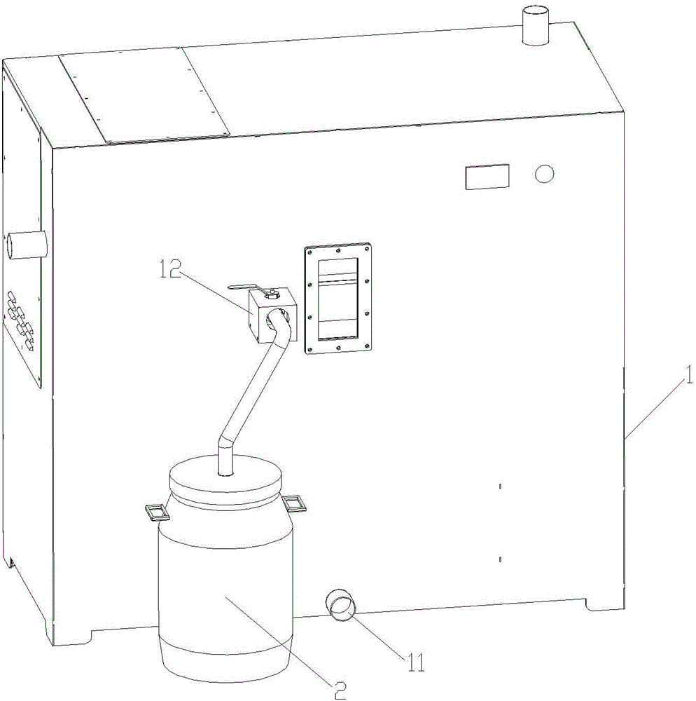
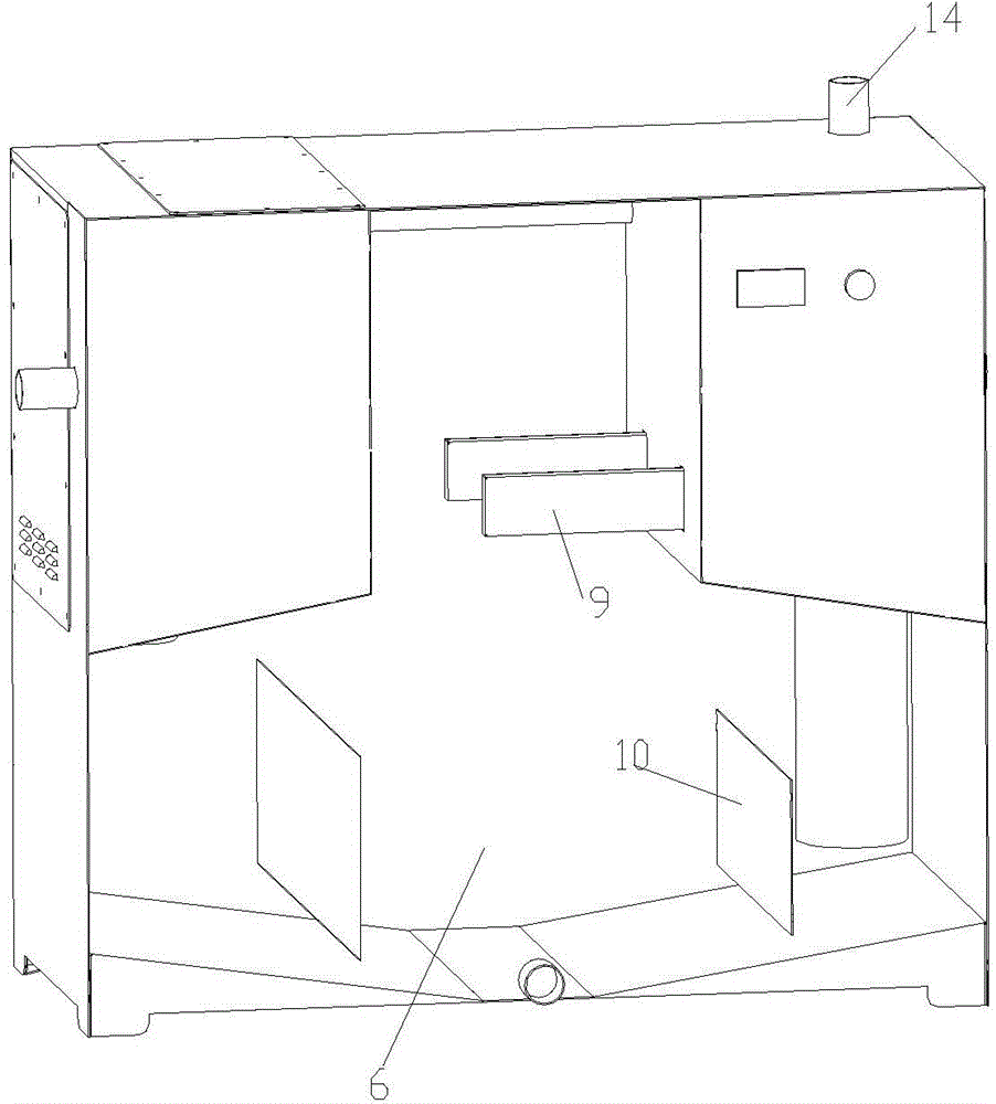
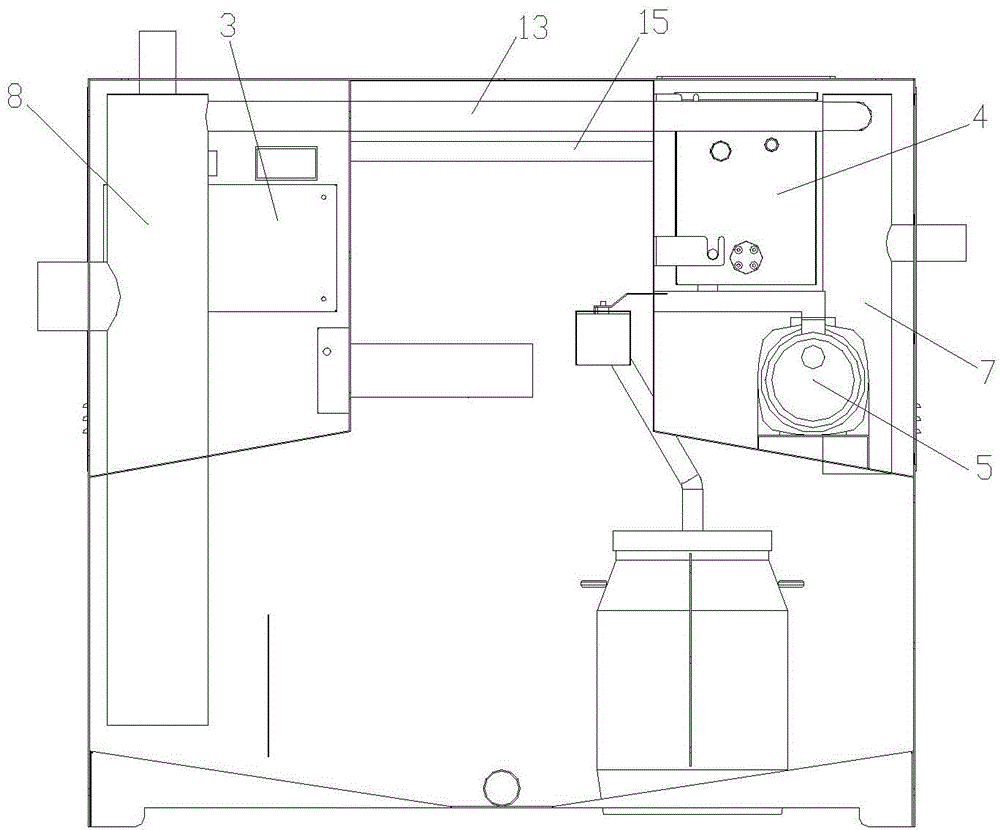
[0014] Please refer to the attached Figures 1 to 3 , the embodiment of the present invention includes:

[0015] A special oil-water separator includes a main box body 1 and an oil storage barrel 2, and an electric control box 3, an oil-water separation device, a heating water tank 4 and a cleaning pump 5 are arranged in the main box body 1. The oil-water separation device comprises a sewage tank 6, a water inlet pipe 7, a water outlet pipe 8, a heating plate 9, a monitor and a temperature detector. Wherein, the middle part of the top plate of the sewage tank 6 is provided with a protruding chamber so that the sewage tank is in a "convex" shape....


PUM


Abstract

The invention relates to a special oil-water separator comprising a main box body and an oil storage barrel, wherein an electric control box, an oil-water separation device, a heating water tank and a cleaning pump are arranged in the main box body; the heating water tank is used for conveying heating water into the oil-water separation device by the cleaning pump; the oil-water separation device comprises a sewage tank, a water inlet pipe, a water outlet pipe, a heating plate, a monitor and a temperature detector; a convex chamber is arranged at the middle of a head plate of the sewage tank; mounting holes for mounting the heating plate, the monitor and the temperature detector are formed in the inner wall of the convex chamber; an oil outlet hole is further formed in the inner wall of the convex chamber; the height of the oil outlet hole is larger than the height of the monitor; the oil outlet hole is connected to the oil storage barrel through a pipeline; an oil outlet valve is arranged at the outside of the oil outlet hole; the water inlet pipe and the water outlet pipe are vertically fixed on both sides of the convex chamber respectively; the top end of the water inlet pipe and the top end of the water outlet pipe are connected via a vent pipe; an air discharge head is further arranged at the top of the water outlet pipe.

Description

technical field [0001] The invention relates to the field of garbage treatment equipment, in particular to a special oil-water separator. Background technique [0002] At present, most cities in my country still use grease traps for sewage treatment, but the problem of oil-water separation in sewage discharge has not been solved fundamentally. In order to solve the above problems, oil-water separation equipment is subject to a wide range of supply and demand. For example, the Chinese invention patent "A Kitchen Garbage Oil-Water Separation Box" has an application number of 201310204976.6, which discloses a cabinet and two partitions symmetrically arranged in the cabinet near the bottom of the cabinet. There is a gap between the partition and the bottom of the cabinet. There are observation windows and inspection ports on the top; heating pipes and electrode rods are arranged inside the chassis; vent holes are opened on the top of the chassis, sewage outlets and return hole...

Claims


Application Information

Patent Timeline
IPC IPC(8): C02F1/40
CPCC02F1/40C02F1/02C02F2209/03
Inventor 钱海荣
Owner SUZHOU MEISHENG ENVIRONMENTAL PROTECTION TECH
Learn More