Device for electrokinetic focusing and electrical detection of particles and chemical species facilitated by a porous electrode

a porous electrode and electrokinetic technology, applied in the field of high-throughput microfluidic devices and methods, can solve the problems of requiring preconcentration, hindering integration into poc devices, and difficult aspects, and achieves high efficiency focusing, increased fluidic stability, and high volumetric throughput.

Pending Publication Date: 2022-02-17
IOWA STATE UNIV RES FOUND
View PDF0 Cites 1 Cited by
  • Summary
  • Abstract
  • Description
  • Claims
  • Application Information

AI Technical Summary

Benefits of technology

[0016]In one aspect, the present disclosure provides a microfluidic device, the device comprising one or more fluidic microchannels wherein the one or more microchannels are connected to at least one inlet and at least one outlet, wherein a background electrolyte solution is infused through at least one inlet, flows through the one or more microchannels, and is withdrawn from at least one outlet. The microchannel(s) further comprise at least one flow-through 3-dimensional (“3D”) flow-through electrode, wherein the 3D electrode comprises an electrode with the addition of conductive microbeads in a bead bed wherein at least a portion of the conductive microbeads is in contact with the electrode and wherein at least a portion of the electrode extends outside of the channel for electrical connection. At least one inlet and at least one outlet are each connected to an electrode, and at least a portion of the conductive microbeads are contained within a primary bead bed which extends at least a portion of the width and length of the microchannel as defined by a bead bed structure within the microchannel. In an aspect, voltage is applied to the inlet and / or outlet electrodes and the 3D electrode for enrichment and separation of charged species at an electric field gradient at the boundary of an ion depleted zone resulting from faradaic processes. The 3D electrode drives charge transfer reactions developing out-of-plane faradaic ion concentration polarization (“fICP”) and formation of an ion depleted zone (“IDZ”) which allows for counter-flow focusing of charged species. The 3D electrode maintains high efficiency focusing by distributing the IDZ across the microchannel cross section. Additionally, the geometric features of the bead bed increase fluidic stability allowing for higher volumetric throughput.

Problems solved by technology

However, biomarkers that serve as indicators for disease detection are often present at a low concentration (fM-pM) and therefore, require preconcentration.
However, despite the success of these preconcentration methods, some aspects remain challenging.
Many existing ICP-based preconcentrators operate at >100 V, which hinders integration into POC devices, as a device that requires such a voltage cannot be powered by a common battery.
Fluidic instability, or vortex flow, which is exacerbated by increased device dimensions, leads to unwanted mixing, ultimately limiting sensitivity.
However, in a tall microchannel or under rapid fluid flow, the IDZ does not extend the full height of the microchannel from the planar electrode.
This phenomenon decreases the efficiency of enrichment.
However, these approaches sacrifice volumetric throughput and are limited by gas bubble formation, respectively.
Nevertheless, these assays are limited in scope because they require the analyte to be fluorescent or to be tagged with a fluorescent label.
The key point is that these detection limits are competitive with fluorescence-based methods but require only simple electrical equipment.
For many such biomedical applications, sensitivity is limited by the volume of fluid that can be ‘swept’ for the analyte within a reasonable timeframe.
Fluidic instability is the primary limitation to scaling devices up for increased volumetric throughput.
When the channel cross section becomes large, mixing driven by fluid vortices drastically decreases the efficiency of enrichment and separation.

Method used


Image

  • Device for electrokinetic focusing and electrical detection of particles and chemical species facilitated by a porous electrode
  • Device for electrokinetic focusing and electrical detection of particles and chemical species facilitated by a porous electrode
  • Device for electrokinetic focusing and electrical detection of particles and chemical species facilitated by a porous electrode

Examples


example 1

[0170]Confirmation of Ion Depletion Zone by the fICP Mechanism

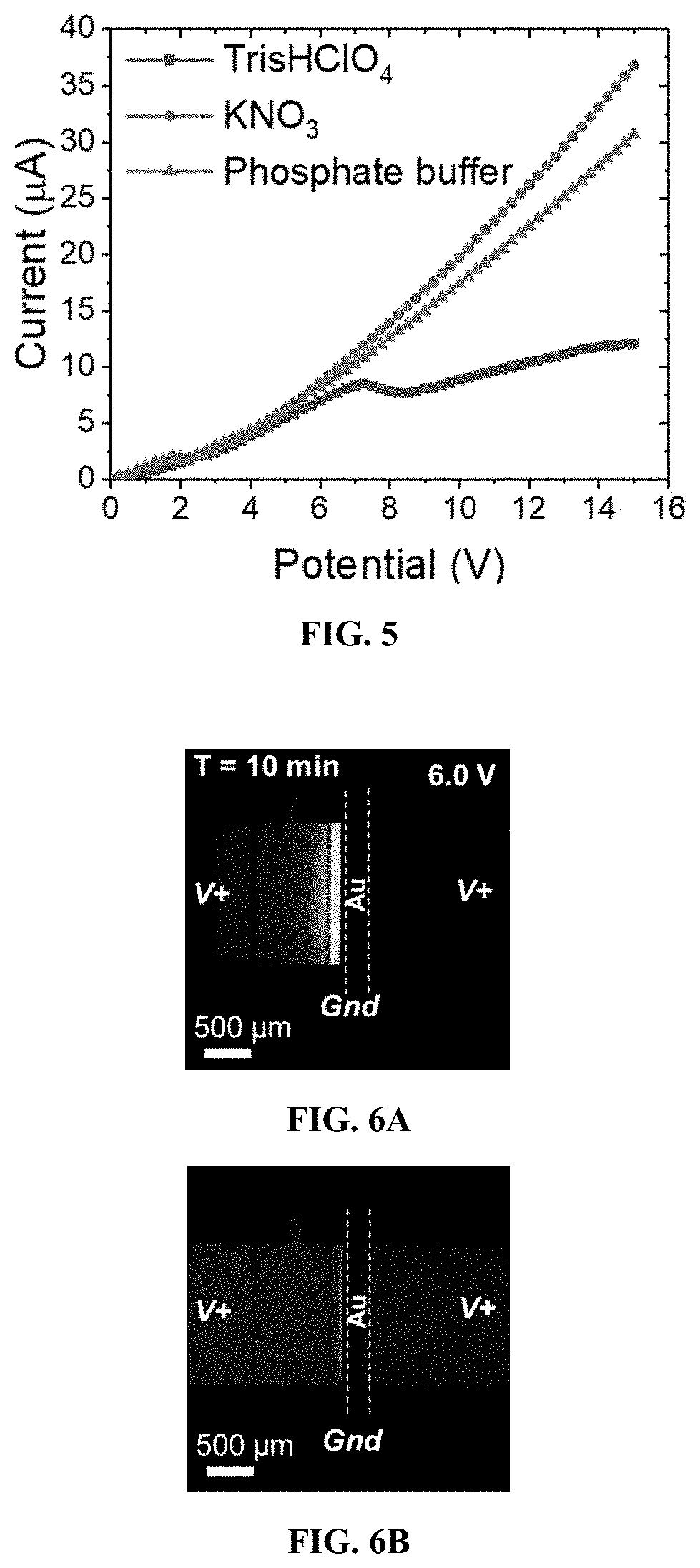
[0171]In this Example, the presence or absence of an IDZ was determined for three distinct background electrolyte (“BGE”) solutions.

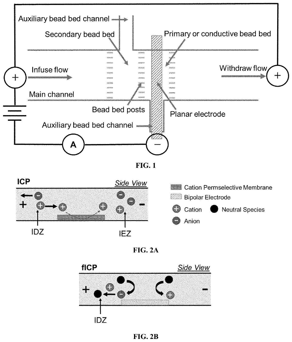
[0172]Exemplary devices were fabricated using the processes as outlined above, and according to FIG. 1, using the dimensions of Exemplary Device Design 1 in Table 1, and a planar Au microband electrode with no beads. In this Example, the main channel was rinsed for 20 minutes with 40.0 mM Tris.HClO4 buffer solution before filling the inlet reservoir with 10.0 μL of a BGE solution spiked with 0.3 μM Texas Red BSA and 10 μM BODIPY2−. The BGE solutions tested include KNO3 (10.0 mM, 1588 μS cm−1), phosphate buffer (10.0 mM, pH 7.4, 2642 μS cm−1), and Tris.HClO4 buffer (40.0 mM, pH 8.3, 878 μS cm−1). Prior to use, devices were conditioned at 3.0 V for 5 minutes, at 200 nL min−1. For ion depletion zone (“IDZ”) growth measurements, the flow rate was decreased to 10 nL min−1 allowing the flow to equi...

example 2

[0176]IDZ Formation with 3D Electrode Structures for fICP with and without a Secondary Upstream Bead Bed

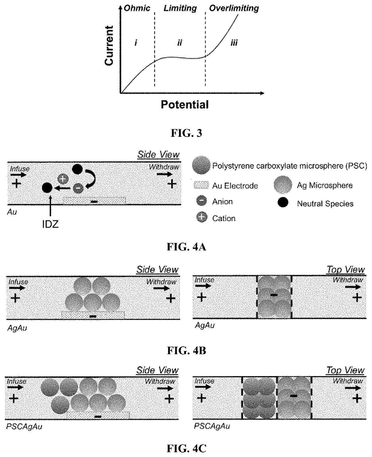
[0177]In this Example, IDZ formation at the planar Au microband electrode is compared with devices having a three-dimensional electrode in the absence (“Ag / Au”) and presence (“PSC / Ag / Au”) of a secondary, upstream PSC bead bed.

[0178]Exemplary devices were fabricated using the processes as outlined above, according to FIG. 1, and using the dimensions of Exemplary Device Design 1 in Table 1. Three exemplary device structures were examined: a device with a planar Au microband electrode and no beads, a device with a 3D electrode comprised of a planar Au microband and Ag beads, and a device with the 3D electrode and an upstream secondary bead bed of PSC beads. These device structures are illustrated in FIG. 4A, FIG. 4B, and FIG. 4C.

[0179]In this Example, the main microchannel was rinsed for 20 minutes with Tris.HClO4 buffer (40.0 mM, pH 8.3). The reservoirs were then filled with 40.0 mM...

example 3

Scalability of the Device

[0184]In this Example, the impact of device scale on concentration enrichment in the PSC / Ag / Au device is investigated.

[0185]Exemplary devices were fabricated using the processes as outlined above, according to FIG. 1, using the dimensions of Exemplary Device Design 2 in Table 1. Both the flow rate and channel width were doubled as compared to the Exemplary Device Design 1 in the previous Examples. The channel was filled with 0.1 μM BODIPY2− in 40.0 mM Tris buffer, and constant fluid flow was established. Then, V+=7.0 V was applied. FIG. 16 is a fluorescence micrograph of the resulting enriched band of tracer dye positioned within the PSC bead bed after 450 seconds following initiation of the applied voltage. FIG. 17 shows the evolution of the EF over this time period. The 80-fold enrichment obtained over 450 seconds is a rate of 0.18-fold / s, which is comparable to the rate (0.13-fold / s) observed in the narrower (1.48 mm-wide) device. This result indicates th...


PUM

PropertyMeasurementUnit
lengthaaaaaaaaaa
heightaaaaaaaaaa
heightaaaaaaaaaa

Abstract

High-throughput microfluidic devices comprising one or more fluidic microchannels each with at least one flow-through 3D structure comprising a 3D electrode, or alternatively a 3D permselective structure, and optional secondary bead bed(s) are disclosed. Such devices can be used for counter-flow focusing of charged species via ion concentration polarization and in situ quantification of electrokinetically enriched charged species from an ionically conductive solution by both optical and electrical detection.

Description

CROSS-REFERENCE TO RELATED APPLICATIONS[0001]This application claims priority under 35 U.S.C. § 119 to provisional application Ser. No. 62 / 706,412, filed Aug. 14, 2020, herein incorporated by reference in its entirety.GOVERNMENT RIGHTS[0002]This invention was made with government support under National Science Foundation Grant No. CHE1849109. The government has certain rights in this invention.SEQUENCE LISTING[0003]The instant application contains a Sequence Listing which has been submitted in ASCII format by electronic submission and is hereby incorporated by reference in its entirety. Said ASCII copy, created on Jun. 8, 2021, is named ANAND_P13288US01_SEQLISTING_ST25.txt and is 4,096 bytes in size.FIELD OF THE INVENTION[0004]The present invention is related to a high-throughput microfluidic device and methods for counter-flow focusing of charged species via ion concentration polarization. Specifically, a microfluidic device that comprises one or more fluidic microchannels each wit...

Claims


Application Information

Patent Timeline
Patent Type & Authority Applications(United States)
IPC IPC(8): G01N1/40A61M1/16G01N1/22
CPCG01N1/40A61M1/1656G01N2001/4038G01N1/2202A61M1/1603A61M1/1696A61M2205/0244B01L3/50273B01L2400/0415B01L2200/0631B01D63/005
Inventor ANAND, ROBBYN K.BERZINA, BEATRISE
Owner IOWA STATE UNIV RES FOUND
Why Eureka
Try Eureka