Nanopore fabrication
a technology of nanopores and fabrication methods, applied in the direction of instruments, membranes, electric/magnetic measuring arrangements, etc., can solve the problems of reducing the permeability of nanopores, affecting background noise, and inherently slow, and achieve the effect of thinning the membran
- Summary
- Abstract
- Description
- Claims
- Application Information
AI Technical Summary
Benefits of technology
Problems solved by technology
Method used
Image

Examples
example 2
Fabrication and Validation
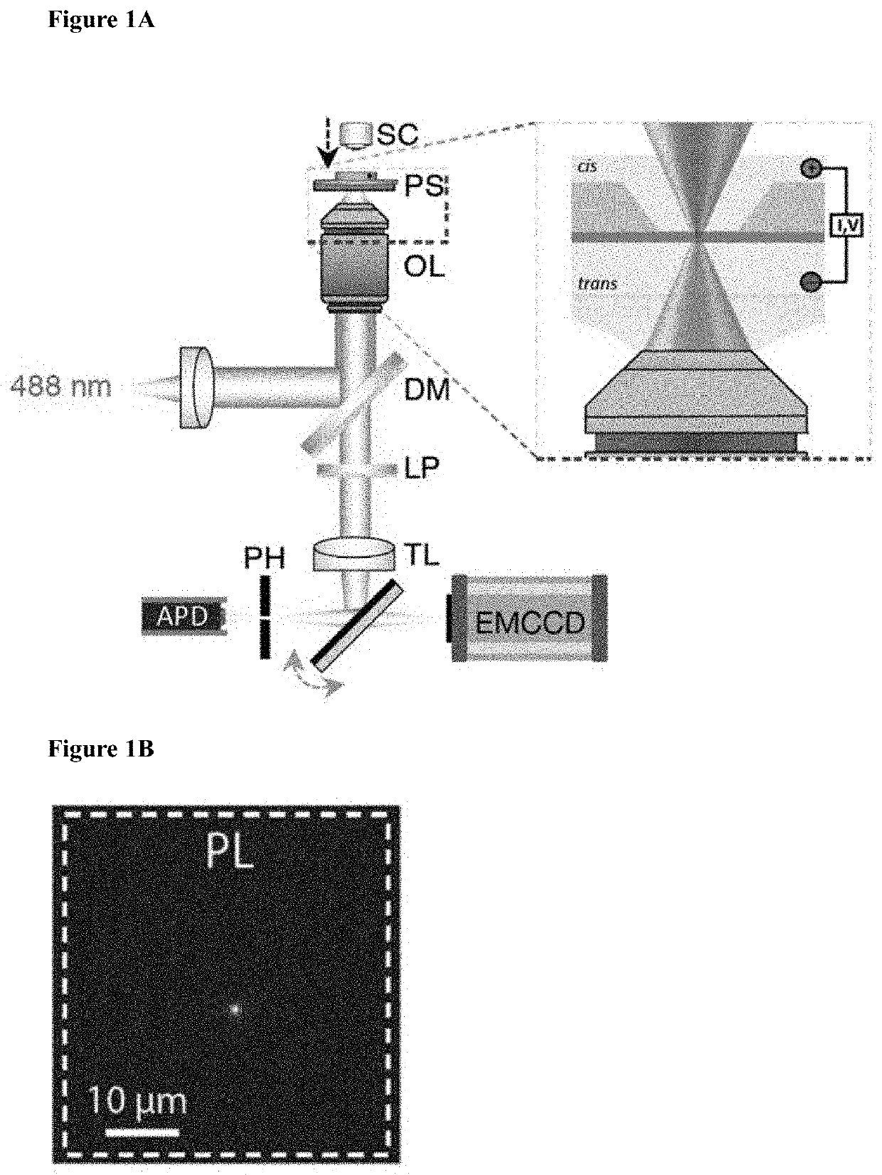
[0286]Based on our observation that a ˜45 milliwatt-intensity blue laser etches SiNx, we attempted to fabricate nanopores by progressively thinning the membrane until the point of nanopore formation. For this, we monitored the ionic current across the membrane, applying a 300 mV transmembrane potential via cis / trans—immersed AgCl electrodes connected to an Axon 200B amplifier. We simultaneously measure the PL as a way to track the fabrication progress. An example experiment with concurrent ionic and PL feedback is given in FIG. 4A. In this example, we observed an increase in ionic current after roughly 145 seconds, which we attribute to the formation of an ionic passageway through the membrane. The current continues to rise until the laser is deactivated, which we associate with nanopore growth. Notably, upon pore formation the ˜45 mW laser also causes an increase in electrolyte conductivity hence, turning the laser off causes the current to drop. The open ...
example 5
t Nanopore Drilling in Si-Rich Membranes
[0304]The strong dependency of thinning on pH and material composition encouraged us to further analyze and characterize this process in order to achieve controlled, ultra-fast, nanopore drilling at low laser intensities. We first immersed a chip with refractive index of 2.3 in high pH buffer (pH 10), exposed it to a 488 nm laser of 7 mW for varying durations, and created a thickness map of the exposed region using EELS. As expected, the thickness maps presented in FIG. 11A show that longer illumination results in increased thinning. This is further demonstrated by comparing the line scans in the middle of each thinned region (FIG. 11B-C). Integrating over this line scan shows a similar trend to the PL measurement during thinning, indicating that the PL can be used to approximate changes in thickness and membrane composition (FIG. 11D). High magnification TEM images revealed that an exposure of ˜15 seconds was enough to create a ˜5 nm pore in ...
example 6
ted In-Situ Fabrication of Nanopore Arrays Using Direct Laser Etching
[0307]The ability to quickly form arrays of nanopores placed at any chosen locations is extremely important for future use of nanopores in high-throughput applications including nucleic-acid sequencing and protein identification. Both the means to electrically address each individual nanopore in an array, as well as parallel optical sensing, have been proposed and developed. Taking advantage of the ultra-fast, in situ drilling process presented hereinabove, we developed a simple hardware-controlled system for drilling an arbitrary array of pores. Specifically, drilling was automated by inputting a list of coordinates and a current gradient threshold. After focusing the laser on the membrane at low intensity, 150 mV was applied across the membrane, and the PL and current were measured in real time. After focusing, the piezo stage moved the membrane to the first coordinates, and the laser intensity was increased to 7...
PUM
| Property | Measurement | Unit |
|---|---|---|
| wavelength | aaaaa | aaaaa |
| wavelength | aaaaa | aaaaa |
| thickness | aaaaa | aaaaa |
Abstract
Description
Claims
Application Information
 - R&D
- Intellectual Property
- Life Sciences
- Materials
- Tech Scout
- Unparalleled Data Quality
- Higher Quality Content
- 60% Fewer Hallucinations
Browse by: Latest US Patents, China's latest patents, Technical Efficacy Thesaurus, Application Domain, Technology Topic, Popular Technical Reports.
© 2025 PatSnap. All rights reserved.Legal|Privacy policy|Modern Slavery Act Transparency Statement|Sitemap|About US| Contact US: help@patsnap.com