
Metal-doped amorphous carbon nitride photocatalytic material and preparation method thereof

Inactive Publication Date: 2021-12-30
SOUTHWEST PETROLEUM UNIV
View PDF0 Cites 2 Cited by
  • Summary
  • Abstract
  • Description
  • Claims
  • Application Information

AI Technical Summary

Benefits of technology

This invention is about a new photocatalytic material and a method to make it using a solid-phase high temperature pyrolysis method. This method involves inducing a carbon nitride amorphous transition by a single atom metal, which causes a transition of the material from a crystalline state to an amorphous state. The result is a material with efficient visible light absorption and carrier channel separation, resulting in an excellent photocatalytic activity. The method is simple, efficient, low-cost, requires no external catalyst, organic solvent, or protective reagent, and is suitable for large-scale commercial production.

Problems solved by technology

However, the graphitic carbon nitride has a weak response to visible light and cannot achieve high-efficiency catalysis of visible light.
However, the amorphous material lacks a long-range ordered structure, which results in a high recombination rate of photoelectron-hole pairs and poor photocatalytic performance.
However, there are still no relevant reports.

Method used


Image

  • Metal-doped amorphous carbon nitride photocatalytic material and preparation method thereof
  • Metal-doped amorphous carbon nitride photocatalytic material and preparation method thereof
  • Metal-doped amorphous carbon nitride photocatalytic material and preparation method thereof

Examples


embodiment 1

[0050](1) Mixing melamine with ammonium molybdate in a ratio of 100:5.5;

[0051](2) heating the above mixture in a tube furnace at 10° C. / min to 550° C., holding the temperature for 4 hours to be cooled to room temperature to obtain the molybdenum-doped amorphous carbon nitride photocatalytic material, marking it as S1, and its performance is tested as shown in Table 1.

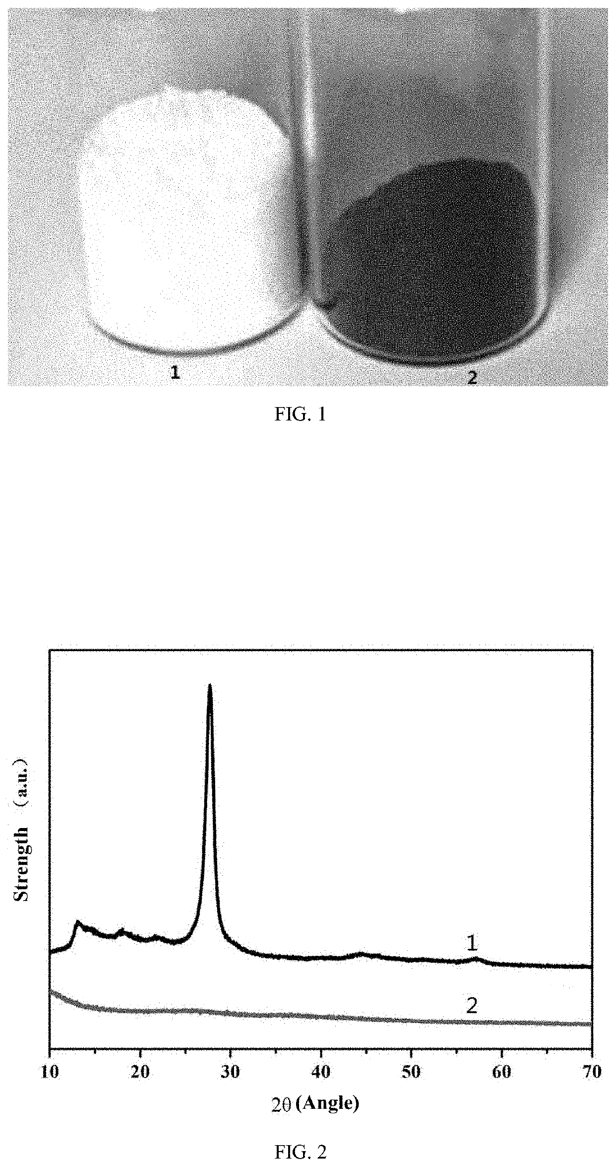
[0052]FIG. 1 is a physical diagram illustrating the photocatalytic material and the ordinary graphitic carbon nitride material prepared in Embodiment 1 of the invention; “1” refers to the ordinary graphitic carbon nitride material, and “2” refers to the photocatalytic material S1 prepared in Embodiment 1 of the invention; as can be seen from the figure, the ordinary graphitic carbon nitride material is pale yellow, and the photocatalytic material S1 prepared in Embodiment 1 of the invention is black.

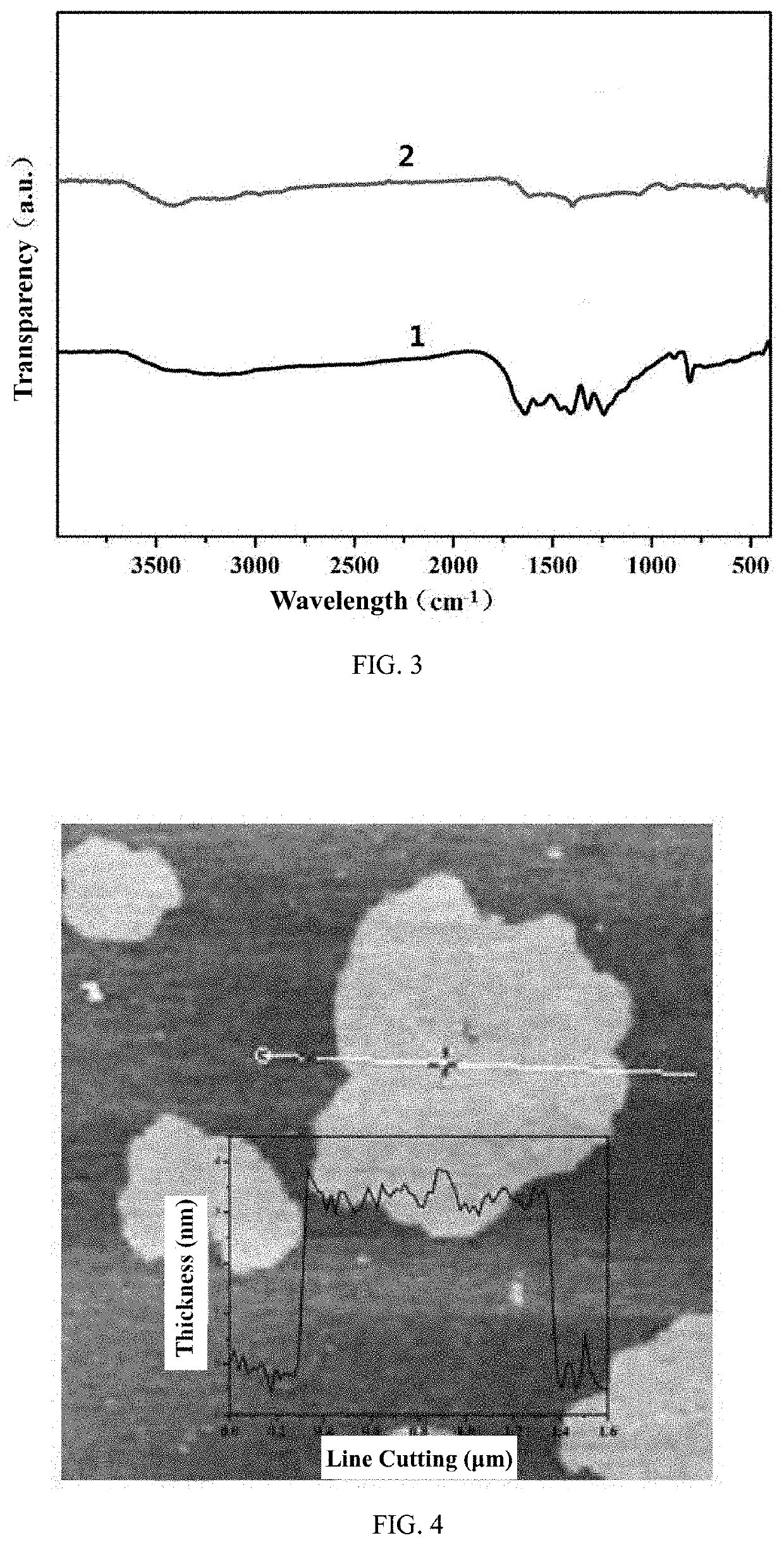
[0053]FIG. 2 is an X-ray diffraction pattern illustrating the photocatalytic material prepared in Embodiment 1 of the inve...

embodiment 2

[0060](1) Mixing melamine with ammonium molybdate in a ratio of 100:10.4;

[0061](2) heating the above mixture in a tube furnace at 10° C. / min to 550° C., holding the temperature for 4 hours to be cooled to room temperature to obtain the molybdenum-doped amorphous carbon nitride photocatalytic material, marking it as S2, and its performance is tested as shown in Table 1.

embodiment 3

[0062](1) Mixing melamine with ammonium molybdate in a ratio of 100:7.9;

[0063](2) heating the above mixture in a tube furnace at 10° C. / min to 550° C., holding the temperature for 4 hours to be cooled to room temperature to obtain the molybdenum-doped amorphous carbon nitride photocatalytic material, marking it as S3 and its performance is tested as shown in Table 1.


PUM

PropertyMeasurementUnit
Temperatureaaaaaaaaaa
Timeaaaaaaaaaa

Abstract

The invention related to photocatalytic material field, and discloses a metal-doped amorphous carbon nitride photocatalytic material and the preparation method thereof. The method comprises: (1) mixing the nitrogen-rich organic matter with the metal salt; (2) calcining the mixture obtained in step (1) to obtain the photocatalytic material; the nitrogen-rich organic matter is selected from one or more of melamine, dicyandiamide, monocyanamide, thiourea, urea, hexamethylenetetramine, and biuret; the metal salt is selected from one or more of an alkali metal salt, an alkaline earth metal salt, and a transition metal salt. The method is simple, efficient, low-cost, requires no external catalyst, organic solvent and protective reagent, and does not require pretreatment of raw materials, and is a preparation method favorable for large-scale commercial production.

Description

BACKGROUND OF THE INVENTION1. Field of the Invention[0001]The invention relates to the photocatalytic material field, and in particular, to a metal-doped amorphous carbon nitride photocatalytic material and the preparation method thereof.2. Description of the Related Art[0002]Photocatalytic technology can convert clean and renewable solar energy into chemical energy and achieve carbon-zero emission, which not only can effectively purify pollutants, but also alleviate the energy crisis; therefore, photocatalytic technology is considered to be one of the most ideal technologies for future world development. In order to achieve this, the preparation of highly active photocatalytic materials has become an urgent problem to be solved. Graphitic carbon nitride is a graphene-like non-metal photocatalytic material mainly composed of nitrogen atoms and carbon atoms; it is simple in preparation process, adjustable in band structure, and excellent in heat resistance and chemical resistance, wh...

Claims


Application Information

Patent Timeline
IPC IPC(8): B01J31/02B01J31/34B01J37/04B01J37/08B01J19/14B01J35/00
CPCB01J31/0235B01J31/34B01J35/004B01J37/082B01J19/14B01J37/04B01J27/24B01J37/08B01J35/39B01J37/084B01J31/0244B01J31/0245B01J35/30
Inventor ZHOU, YINGZHANG, RUIYANGLI, PENGHUIZHANG, QIANYU, SHANWANG, FANG
Owner SOUTHWEST PETROLEUM UNIV
Learn More