
Process for separating chlorinated methanes

Active Publication Date: 2011-10-20
BLUE CUBE IP
View PDF2 Cites 0 Cited by
  • Summary
  • Abstract
  • Description
  • Claims
  • Application Information

AI Technical Summary

Benefits of technology

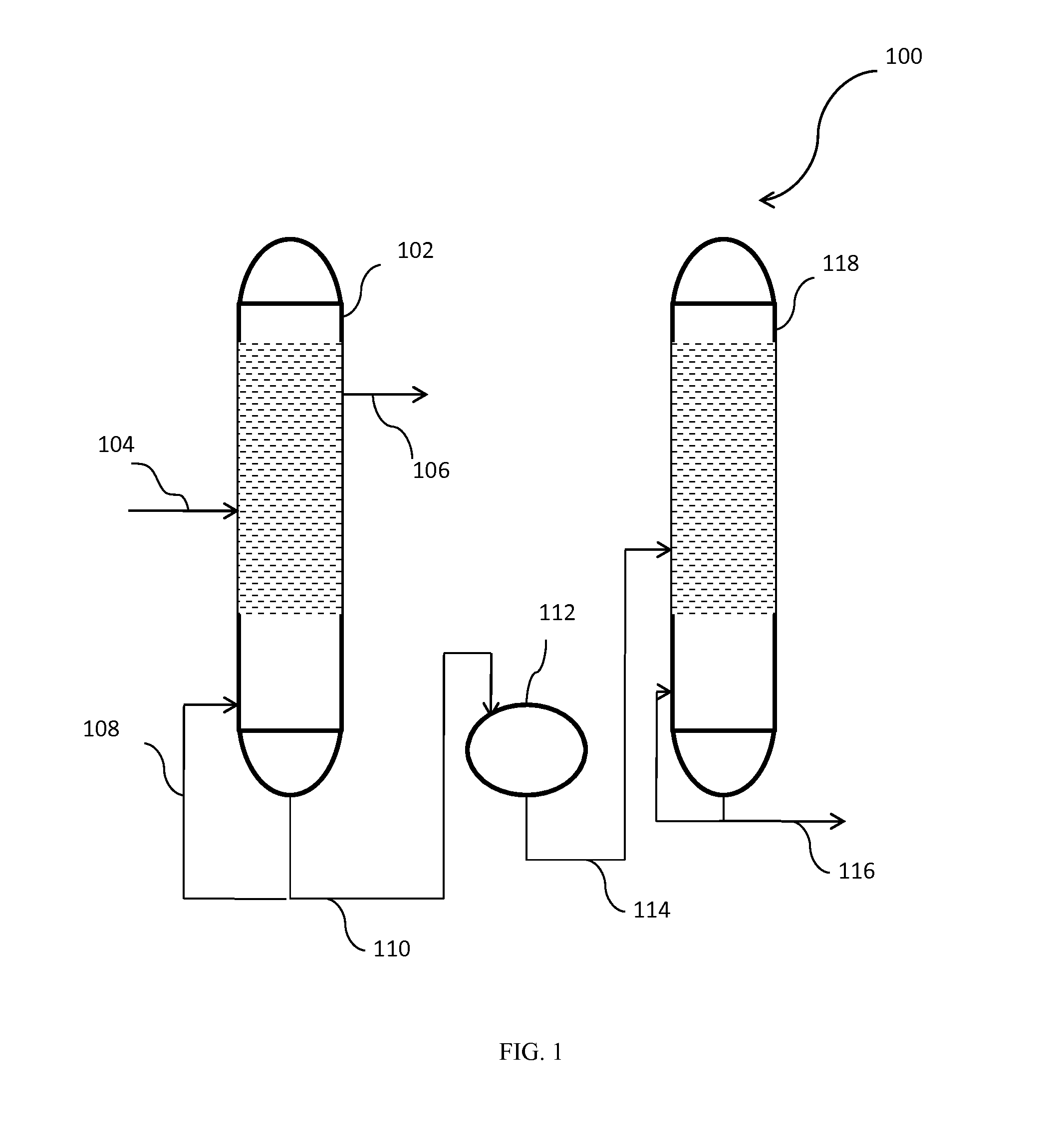
[0005]The present invention provides such processes. More particularly, the present invention provides processes for separating at least two chlorinated methanes within a process stream. The processes make use of a dividing wall column, so that a more efficient separation than can be achieved with other types of separation units. Fewer separation units, or separations, are required to arrive at one or more commercially acceptable end-products and time, space, capital, and energy cost savings are provided.
[0007]The cost savings provided by the separation process provided herein may be leveraged by incorporating the separation process into a process for producing chlorinated methanes. More particularly, utilization of the present separation process within a process for producing chlorinated methanes can reduce the pieces of equipment required in the production process. Even more particularly, the separation process provided herein may replace, in whole or in part, the distillation segment typically included in a conventional process for the production of chlorinated methanes.

Problems solved by technology

In many such processes, the additional products and / or byproducts produced typically have very similar chemical properties so that separation of the desired end product(s) can be difficult to perform.
Suitable separation techniques can also be expensive—conventional distillation is known to be costly in time, energy, space and equipment requirements.
The overall process footprint and cost of operation of these conventional processes is significant and can become prohibitive.

Method used


Image

  • Process for separating chlorinated methanes
  • Process for separating chlorinated methanes
  • Process for separating chlorinated methanes

Examples


example 1

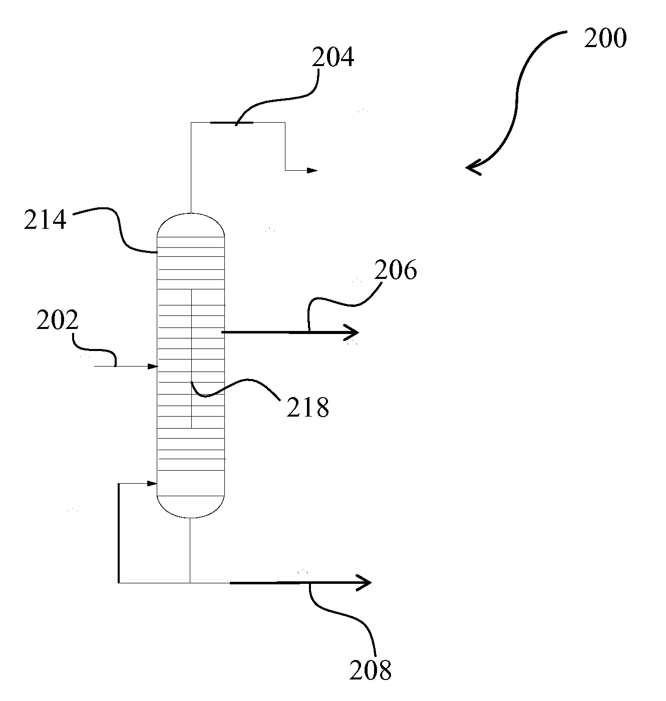
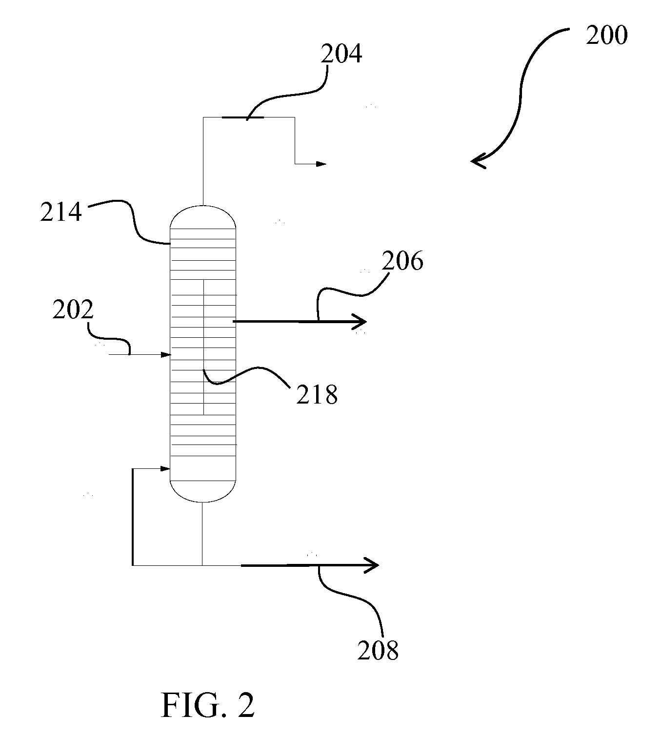
[0039]In this example, a feedstream comprising chlorinated methanes and having a flow rate of about 25000 kg / hr is provided to a dividing wall column similar to that shown in FIG. 2.

[0040]More particularly, the feedstream comprises about 78 wt % dichloromethane, about 19 wt % chloroform, and about 3 wt % carbon tetrachloride. The dividing wall column inlet temperature is about 125° C., the top temperature is about 68° C. and the column is at a pressure of about 2 bar absolute.

[0041]Upon exit from the dividing wall column 214, the upper product stream (204 in FIG. 2) has a mass flow rate of about 20250 kg / hr and comprises about substantially pure dichloromethane, having less than 10 ppm chloroform and only trace amounts of carbon tetrachloride. The mid product stream (206 in FIG. 2) has a mass flow rate of about 4150 kg / hr and comprises substantially pure chloroform, having less than 10 ppm dichloromethane and less than 10 ppm carbon tetrachloride. Finally, the bottom product stream ...


PUM


Abstract

The present invention relates to a process for separating chlorinated methanes utilizing a dividing wall column. Processes and manufacturing assemblies for generating chlorinated methanes are also provided, as are processes for producing products utilizing the chlorinated methanes produced and / or separated utilizing the present process(es) and / or assemblies.

Description

FIELD[0001]The present invention relates to a process for separating chlorinated methanes utilizing a dividing wall column. Processes for generating chlorinated methanes are also provided, as are processes for producing products utilizing the chlorinated methanes produced and / or separated utilizing the present process(es).BACKGROUND[0002]Many, if not all, chemical processes do not result in a purified end product, but rather, typically produce a family of products, or at least a single product that must be further purified to a saleable form. In many such processes, the additional products and / or byproducts produced typically have very similar chemical properties so that separation of the desired end product(s) can be difficult to perform. Suitable separation techniques can also be expensive—conventional distillation is known to be costly in time, energy, space and equipment requirements. Further, in order to provide multiple end products, multiple distillations may typically be req...

Claims


Application Information

Patent Timeline
IPC IPC(8): C07C17/38B01D3/00
CPCB01D3/141C07C17/383C07C19/03C07C19/041C07C19/04B01D3/14
Inventor PENDERGAST, JR., JOHN G.WHITE, WILLIAM S.AVILLA, ANTHONY R.LUEBBE, THOMAS U.
Owner BLUE CUBE IP
Learn More