Decorative Surface Covering Element, Surface Covering Element Covering, and Method of Producing Such a Decorative Surface Covering Element

a surface covering element and decorative technology, applied in the field of decorative surface covering elements, can solve the problems of increasing labor and overall cost of the project, affecting and affecting the appearance of the surface, so as to improve the surface scratch resistance, glossiness, antimicrobial resistance and other properties of the product, and increase the durability of the tiles.

Active Publication Date: 2021-09-16
NORTHANN BUILDING SOLUTIONS LLC
View PDF0 Cites 3 Cited by
  • Summary
  • Abstract
  • Description
  • Claims
  • Application Information

AI Technical Summary

Benefits of technology

[0035]The covering structure is preferably at least partially covered by a lacquer layer (wear layer). The lacquer layer can comprise any suitable known abrasion-resistant material, such as an abrasion-resistant macromolecular material coated onto the layer beneath it, or a known ceramic bead coating. If the wear layer is furnished in layer form, it can be bonded to the layer beneath it. The wear layer can also comprise an organic polymer layer and/or inorganic material layer, such as an ultraviolet coating or a combination of another organic polymer layer and an ultraviolet coating. For example, an ultraviolet paint capable of improving the surface scratch resistance, glossiness, antimicrobial resistance and other properties of the product. Other organic polymers including polyvinyl chloride resins or other polymers such as vinyl resins, and a suitable amount of plasticizing agent and other processing additives can be included, as needed. In an embodiment of a surface covering element according to the invention, at least at least a part of the indentations of the base layer is left uncovered by the lacquer layer. In this manner, a further embossing effect (relief effect) can be achieved, and, moreover, glossy and matt areas may be created in this manner, which may further contribute to a desired aesthetical appearance of the surface covering element as such. Here, for example, in case the décor image is formed by artificial tiles separated by grouts, the artificial tiles may be covered by the lacquer layer to provide these tiles a glossy effect, while the grouts are left substantially uncovered by the lacquer layer to maintain a more matt appearance.
[0036]It is imaginable that at least a part of at least one decorative layer is printed, preferably digitally printed, directly onto the upper side of the core. It is also imaginable that the upper side of the core is provided with at least one carrier layer, preferably formed by at least one primer or a film, wherein at least a part of the decorative layer is printed, preferably digitally printed, directly onto the carrier layer. The carrier layer can be affixed directly or indirectly (via one or more intermediate layers) onto the core. In case a primer is applied, then it is imaginable to apply at least two different primers, such as a glossy primer and a matt primer, which are position-selectively applied, side by side (adjacently), onto the core, preferably aligned in register with the decorat...

Problems solved by technology

Forming this separation between tiles is often tedious and requires the use of spacers to ensure uniformity and alignment of the tiles.
In general, the process of installing tile and creating the grout line involves a significant amount of time, which adds to the labor and overall cost of the project.
While this slight separation may be observable and in some cases may appear as a small seam or even as a micro groove, these types of known tile...

Method used


Image

  • Decorative Surface Covering Element, Surface Covering Element Covering, and Method of Producing Such a Decorative Surface Covering Element
  • Decorative Surface Covering Element, Surface Covering Element Covering, and Method of Producing Such a Decorative Surface Covering Element
  • Decorative Surface Covering Element, Surface Covering Element Covering, and Method of Producing Such a Decorative Surface Covering Element

Examples


Embodiment Construction

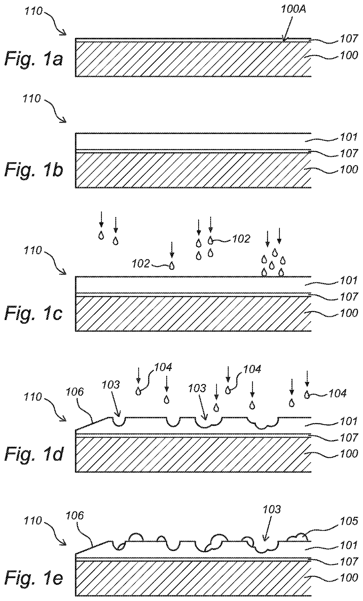
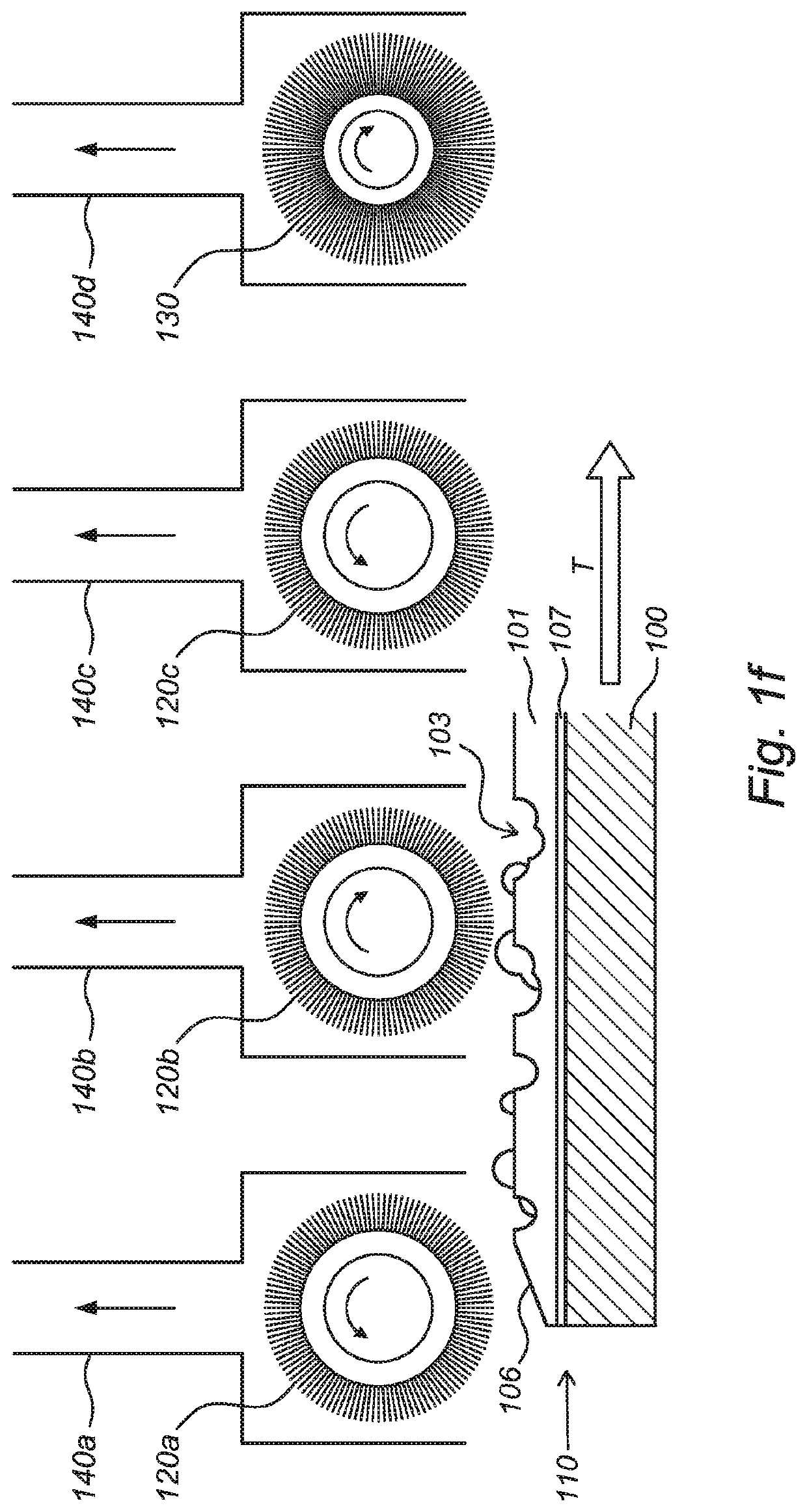
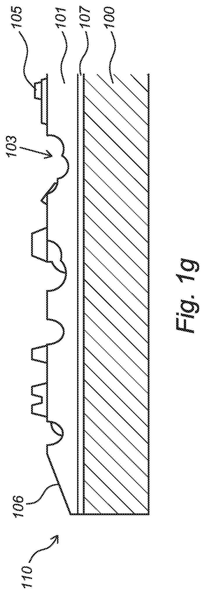
[0063]FIGS. 1a-1g show subsequent steps of a method according to the present invention. FIG. 1a shows a schematic representation of a cross section of a decorative panel (110) as an example of a surface covering element according to the invention. The figure shows the core (100) of the panel (110). The core (100) is typically substantially rigid, and may possibly comprises at least one polymer and / or at least one wood-based material. A decorative layer (107), in particular a decor image, is formed, preferably by means of digital printing, onto the upper side (100A) of the core (100) by means of printing, in particular digital printing. FIG. 1b show that a liquid base layer (101) is applied on the déor image formed at the upper side (100A) of the panel (110). The liquid forming the liquid base layer (101) is for example a UV sealer. The liquid base layer (101) generally has a relatively high surface tension in order to allow precise embossing in the liquid base layer (101). FIG. 1c s...


PUM

PropertyMeasurementUnit
Fractionaaaaaaaaaa
Fractionaaaaaaaaaa
Heightaaaaaaaaaa

Abstract

The invention relates to a decorative surface covering element, in particular a floor panel, ceiling panel or wall panel. The invention also relates to a panel covering, such as a floor covering, ceiling covering or wall covering, comprising a plurality of panels according to the invention. The invention further relates to a method of producing a decorative surface covering element according to the invention.

Description

CROSS-REFERENCE TO RELATED APPLICATION[0001]This application claims priority to The Netherlands Patent Application No. 2025115 filed Mar. 12, 2020, the disclosure of which is hereby incorporated by reference in its entirety.BACKGROUND OF THE INVENTIONField of the Invention[0002]The invention relates to a decorative surface covering element, in particular a floor surface covering element, ceiling surface covering element or wall surface covering element. The invention also relates to a surface covering element covering, such as a floor covering, ceiling covering or wall covering, comprising a plurality of surface covering elements according to the invention. The invention further relates to a method of producing a decorative surface covering element according to the invention.Description of Related Art[0003]During the construction of a home, building or other structure, there will almost always be an unfinished floor surface such as a slab of concrete, a wood sub-structure or the lik...

Claims


Application Information

Patent Timeline
IPC IPC(8): E04F13/08E04F15/02
CPCE04F13/0873E04F13/0894E04F13/0866E04F2201/043E04F2201/0138E04F2201/0153E04F15/02038E04F13/072E04F13/0876E04B9/04E04F15/02E04F13/0871E04F15/02033E04F15/02161E04F15/107E04F15/105E04F13/18
Inventor LI, LIN
Owner NORTHANN BUILDING SOLUTIONS LLC
Why Eureka
Try Eureka