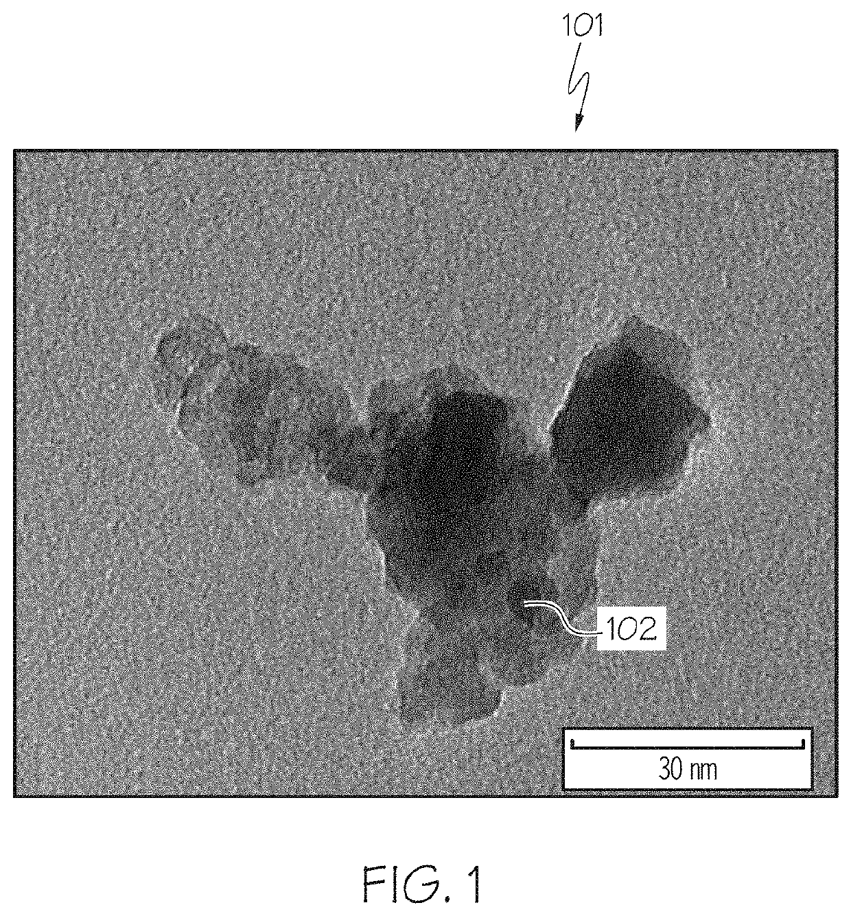
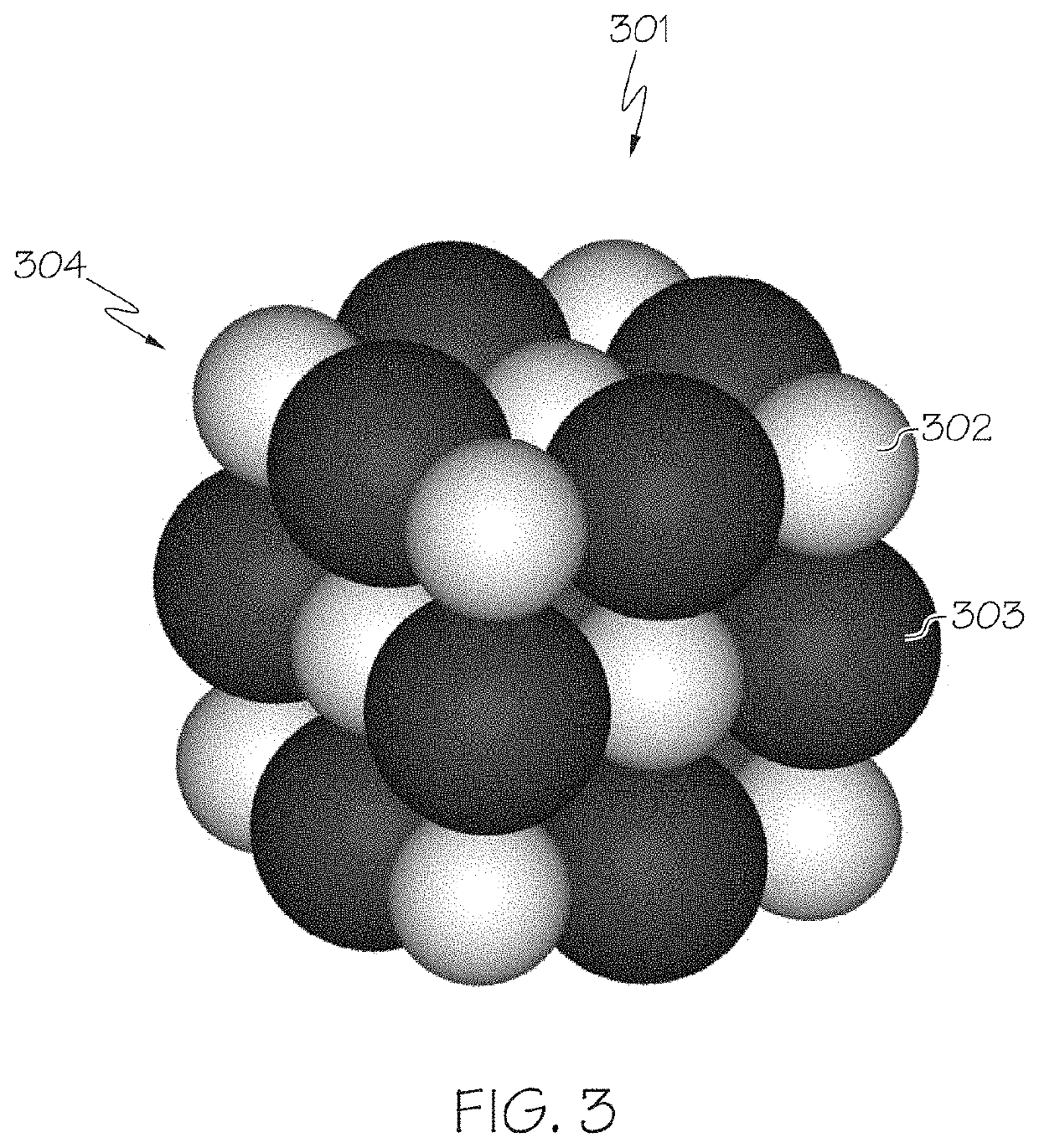
NANO particle agglomerate reduction to primary particle
a technology of nanoparticles and agglomerates, which is applied in the direction of fixed capacitors, chemical/physical processes, solid separation, etc., can solve the problems of difficult separation of agglomerated nanoparticles into individual primary nanoparticles, and the inability to separate agglomerated nanoparticles using conventional particle reduction methods, etc., to achieve enhanced performance, reduce the size of agglomerated nanoparticles, and high surface area
- Summary
- Abstract
- Description
- Claims
- Application Information
AI Technical Summary
Benefits of technology
Problems solved by technology
Method used
Image


Examples
Embodiment Construction
[0078]As required, detailed embodiments are disclosed herein; however, it is to be understood that the disclosed embodiments are merely examples and that the devices, systems and methods described herein can be embodied in various forms. Therefore, specific structural and functional details disclosed herein are not to be interpreted as limiting, but merely as a basis for the claims and as a representative basis for teaching one of ordinary skill in the art to variously employ the disclosed subject matter in virtually any proprietary detailed structure and function. Further, the terms and phrases used herein are not intended to be limiting, but rather, to provide an understandable description. Additionally, unless otherwise specifically expressed or clearly understood from the context of use, a term as used herein describes the singular and / or the plural of that term.
[0079]The terms “a” or “an”, as used herein, are defined as one or more than one. The term “plurality”, as used herein...
PUM
| Property | Measurement | Unit |
|---|---|---|
| Temperature | aaaaa | aaaaa |
| Temperature | aaaaa | aaaaa |
| Temperature | aaaaa | aaaaa |
Abstract
Description
Claims
Application Information
 - Generate Ideas
- Intellectual Property
- Life Sciences
- Materials
- Tech Scout
- Unparalleled Data Quality
- Higher Quality Content
- 60% Fewer Hallucinations
Browse by: Latest US Patents, China's latest patents, Technical Efficacy Thesaurus, Application Domain, Technology Topic, Popular Technical Reports.
© 2025 PatSnap. All rights reserved.Legal|Privacy policy|Modern Slavery Act Transparency Statement|Sitemap|About US| Contact US: help@patsnap.com