Liquid crystal phase shifter, liquid crystal antenna and manufacturing method of liquid crystal phase shifter
a manufacturing method and technology of liquid crystal antenna, applied in the field of wireless communication, can solve the problems of reducing the performance of the antenna, poor signals, so as to achieve the effect of reducing the dielectric loss, poor signals, and increasing the dielectric loss
- Summary
- Abstract
- Description
- Claims
- Application Information
AI Technical Summary
Benefits of technology
Problems solved by technology
Method used
Image

Examples
embodiment i
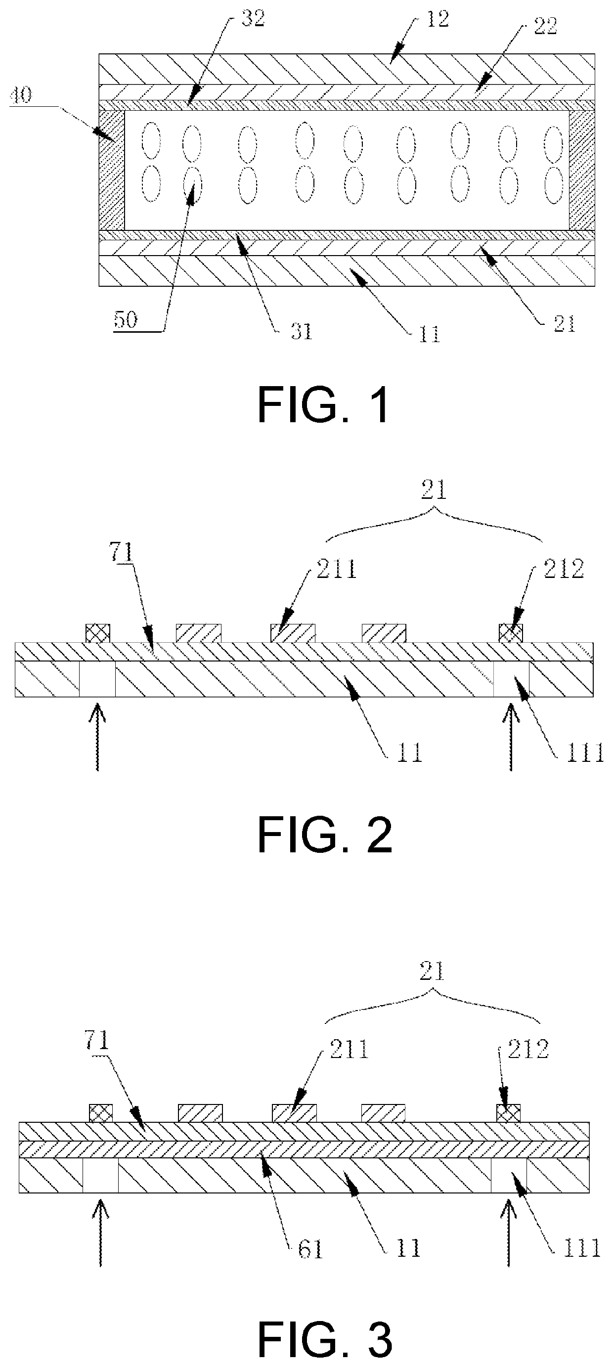
[0048]As shown in FIG. 1, illustrating Embodiment I of the present disclosure, the present specific embodiment provides a liquid crystal phase shifter. The liquid crystal phase shifter includes a first substrate 11 and a second substrate 12 which are disposed oppositely, and further includes a liquid crystal layer 50 located between the first substrate 11 and the second substrate 12.
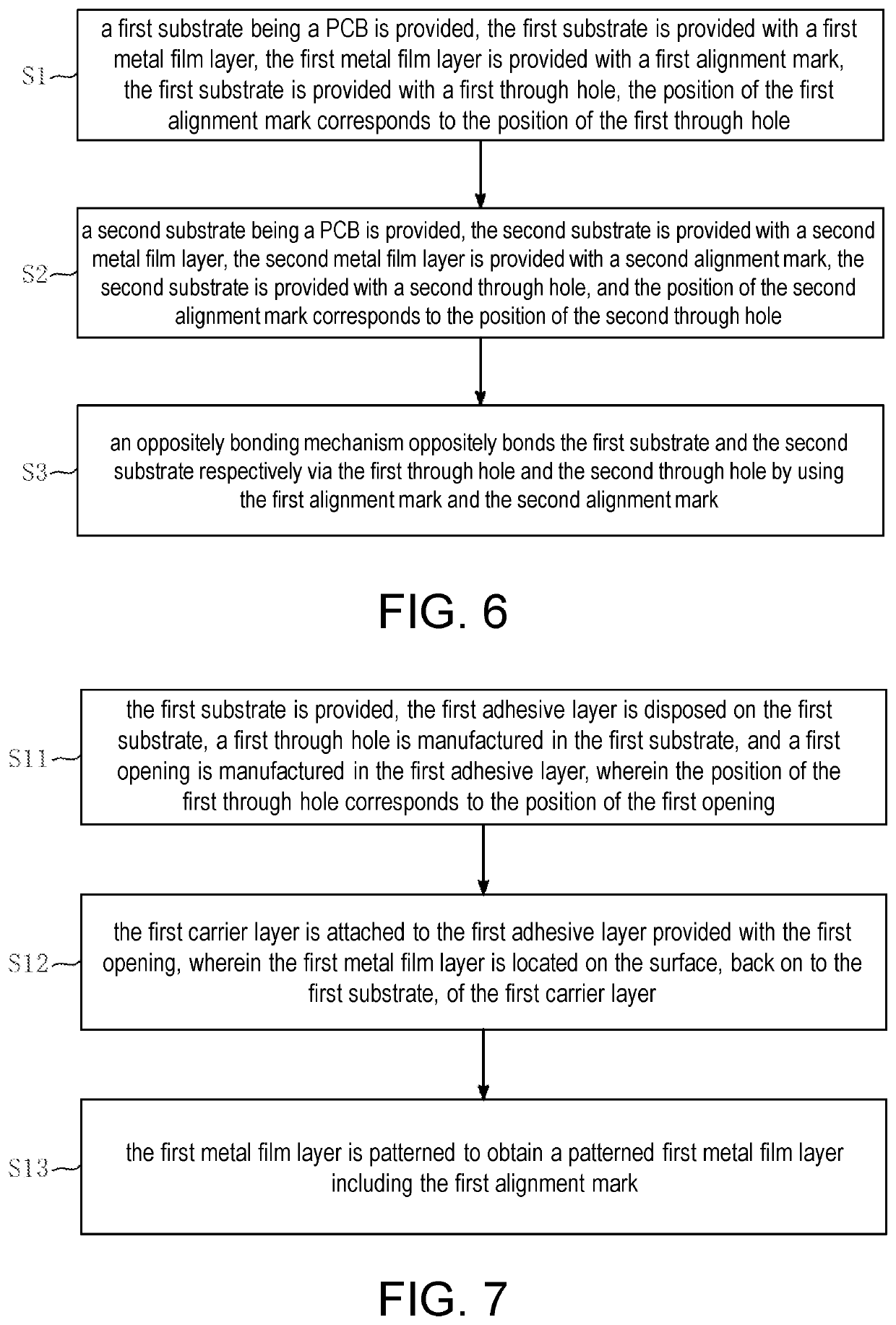
[0049]Sealant 40 is further disposed between the first substrate 11 and the second substrate 12. The sealant 40 is located at the edges of the first substrate 11 and the second substrate 12, and is used for sealing the liquid crystal layer 50. Preferably, supports containing plastic balls and the epoxy sealant 40 are distributed in the liquid crystal layer 50.
[0050]The first substrate 11 is provided with a first conductive layer, and the second substrate 12 is provided with a second conductive layer.
[0051]The side of the first substrate 11 facing the second substrate 12 is provided with a first metal fil...
embodiment ii
[0091]The present specific embodiment provides a liquid crystal antenna. The liquid crystal antenna includes the liquid crystal phase shifter in Embodiment I. The liquid crystal antenna further includes an antenna radiation unit used for radiating a microwave signal, thereby realizing feed-in and feed-out of the microwave signal.
[0092]In the present embodiment, the side, away from the second substrate 12, of the first substrate 11 is provided with an antenna radiation unit. The antenna radiation unit is made of a high-conductivity material. The antenna radiation unit may be a rectangular, round, or square patch, may realize corner cutting, and may also be attached to the liquid crystal phase shifter by a patch process. Or, a more preferable solution is that the antenna radiation unit is a patterned third metal film layer disposed on the side, away from the second substrate 12, of the first substrate 11.
embodiment iii
[0093]The present specific embodiment provides a manufacturing method of the liquid crystal phase shifter in Embodiment I. As shown in FIG. 6, the manufacturing method of the liquid crystal phase shifter includes the following steps.
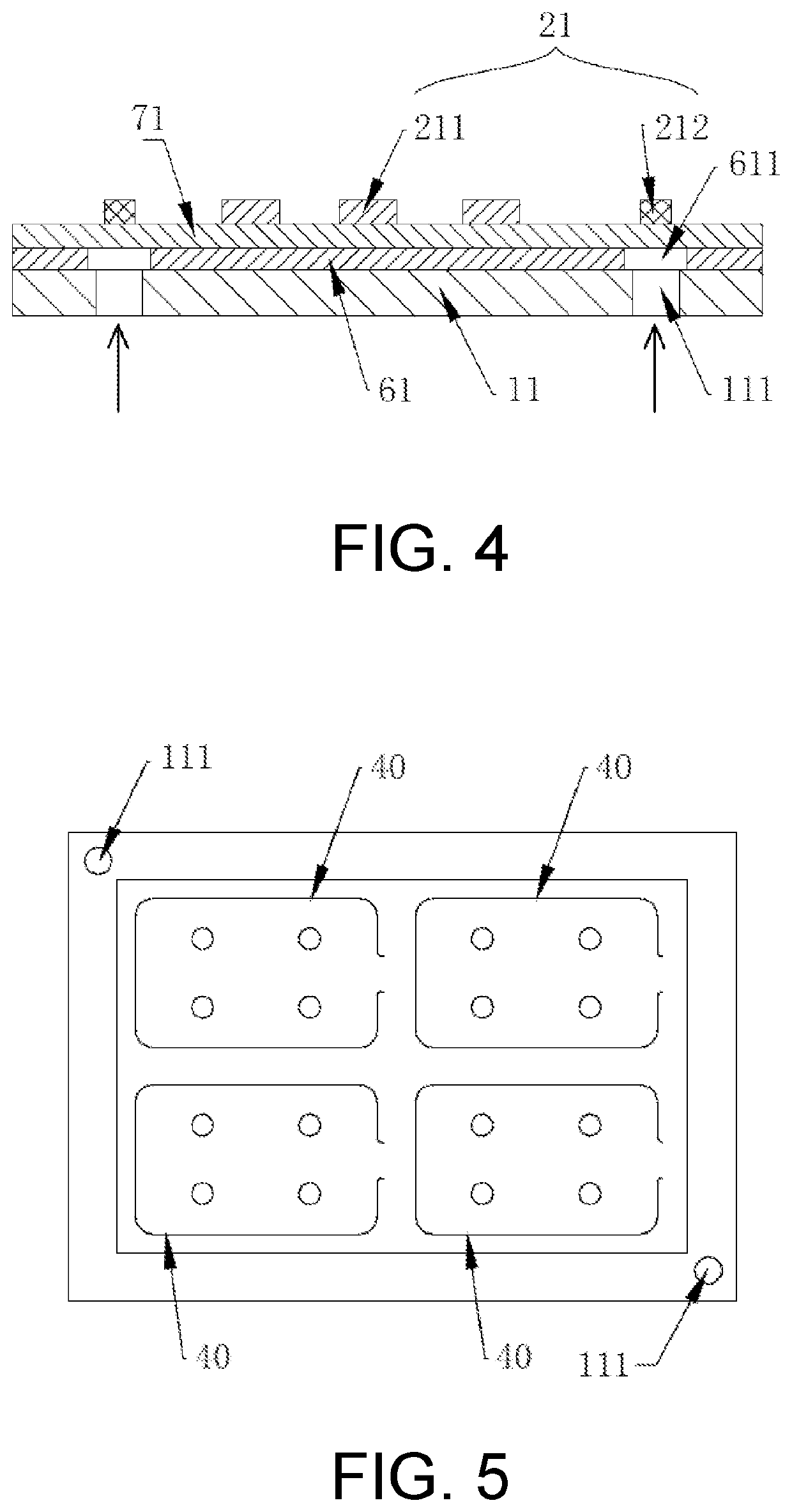
[0094]S1: a first substrate 11 being a PCB is provided. The first substrate 11 is provided with a first metal film layer 21.
[0095]The first metal film layer 21 is provided with a first alignment mark 212. The first substrate 11 is provided with a first through hole 111. The position of the first alignment mark 212 corresponds to the position of the first through hole 111.
[0096]S2: a second substrate 12 being a PCB is provided. The second substrate 12 is provided with a second metal film layer 22, the second metal film layer 22 is provided with a second alignment mark. The second substrate 12 is provided with a second through hole, and the position of the second alignment mark corresponds to the position of the second through hole.
[0097]S3: an oppositely ...
PUM
| Property | Measurement | Unit |
|---|---|---|
| frequency | aaaaa | aaaaa |
| thicknesses | aaaaa | aaaaa |
| transparent | aaaaa | aaaaa |
Abstract
Description
Claims
Application Information
 - R&D
- Intellectual Property
- Life Sciences
- Materials
- Tech Scout
- Unparalleled Data Quality
- Higher Quality Content
- 60% Fewer Hallucinations
Browse by: Latest US Patents, China's latest patents, Technical Efficacy Thesaurus, Application Domain, Technology Topic, Popular Technical Reports.
© 2025 PatSnap. All rights reserved.Legal|Privacy policy|Modern Slavery Act Transparency Statement|Sitemap|About US| Contact US: help@patsnap.com