Pellicle frame, pellicle, and method of producing pellicle frame
a technology which is applied in the field of pellicle and pellicle, can solve the problems of difficult to detect heterogeneous parts, difficult to form uniform coating films, and sometimes remarkably low yield, so as to increase the exposure light exposure amount, facilitate appearance inspection, and improve yield
- Summary
- Abstract
- Description
- Claims
- Application Information
AI Technical Summary
Benefits of technology
Problems solved by technology
Method used
Image
Examples
example 1
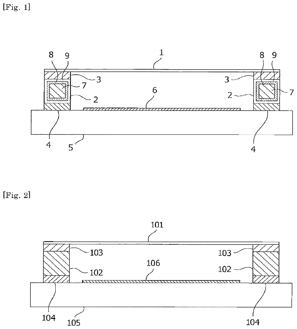
[0068]First, an aluminum-made frame having frame external dimensions of 149 mm×115 mm×4.5 mm and a frame thickness of 2 mm was prepared as a frame base of a pellicle. A surface of this frame base was subjected to sandblasting. The sandblasting was performed by blowing glass beads (30 to 100 μm) with a sandblasting apparatus at a discharge pressure of 1.5 kg for 10 minutes.
[0069]Subsequently, an anodized film (alumite) having a film thickness of 7.0 μm was formed on the frame base by adopting a sulfuric acid method. An electrolysis bath used for the formation of the anodized film was 15% by mass sulfuric acid, and the method was performed at an electrolysis voltage of 20 V and a quantity of electricity of 15 c / cm2 for a treatment time of 20 minutes.
[0070]As for this anodized film, the frame material after anodizing was immersed in a dye solution of “TAC420” (manufactured by Okuno Chemical Industries Co., Ltd) having been regulated to a predetermined concentration and dyed under a tre...
example 2
[0077]A pellicle frame was produced in the same manner as in Example 1, except that the anodized film (alumite) was formed so as to have a film thickness of 2.0 μm. The anodized film was subjected to coloring; however, the color was slightly pale, and the pellicle frame had an L value of 32. In addition, a transmittance of the transparent polymer electrodeposition coating film in a visible light region as measured in the same manner as in Example 1 was 83%.
[0078]Similarly, ten pellicle frames were produced and subjected to appearance inspection. As a result, in all of the frames, neither color unevenness observed in the case where a transparent polymer electrodeposition coating film is heterogeneous nor surface abnormality observed in the case where a transparent polymer electrodeposition coating film is not formed was perceived.
[0079]The inside face of the frame of a pellicle produced in the same manner as in Example 1 was irradiated with an ArF laser set to 5 mJ / cm2 / pulse and 500 ...
example 3
[0082]A pellicle frame was produced in the same manner as in Example 1, except that the anodized film (alumite) was formed so as to have a film thickness of 3.0 μm. The anodized film was colored black, and the pellicle frame had an L value of 29. In addition, a transmittance of the transparent polymer electrodeposition coating film in a visible light region as measured in the same manner as in Example 1 was 82%.
[0083]Similarly, ten pellicle frames were produced and subjected to appearance inspection. As a result, in all of the frames, neither color unevenness observed in the case where a transparent polymer electrodeposition coating film is heterogeneous nor surface abnormality observed in the case where a transparent polymer electrodeposition coating film is not formed was perceived.
[0084]The inside face of the frame of a pellicle produced in the same manner as in Example 1 was irradiated with an ArF laser set to 5 mJ / cm2 / pulse and 500 Hz. After elapsing 30 minutes after carrying o...
PUM
| Property | Measurement | Unit |
|---|---|---|
| visible light transmittance | aaaaa | aaaaa |
| temperature | aaaaa | aaaaa |
| temperature | aaaaa | aaaaa |
Abstract
Description
Claims
Application Information
 - R&D
- Intellectual Property
- Life Sciences
- Materials
- Tech Scout
- Unparalleled Data Quality
- Higher Quality Content
- 60% Fewer Hallucinations
Browse by: Latest US Patents, China's latest patents, Technical Efficacy Thesaurus, Application Domain, Technology Topic, Popular Technical Reports.
© 2025 PatSnap. All rights reserved.Legal|Privacy policy|Modern Slavery Act Transparency Statement|Sitemap|About US| Contact US: help@patsnap.com

