Light intensity fluctuation-insensitive projection objective wave aberration detection device and detection method thereof

Active Publication Date: 2021-07-08
SHANGHAI INST OF OPTICS & FINE MECHANICS CHINESE ACAD OF SCI
View PDF0 Cites 0 Cited by
  • Summary
  • Abstract
  • Description
  • Claims
  • Application Information

AI Technical Summary

Benefits of technology

The present invention aims to overcome the current technology's flaws by providing a light intensity fluctuation-insensitive projection objective wave aberration detection device and a detection method. This device and method can detect waves of light accurately even if the light source's brightness changes, thus improving detection precision and speed. Further, the invention simplifies the device control system and reduces the complexity of the overall system. The detection device can use the same design and processing method as existing devices, making it applicable in both single-channel and multi-channel detection. Overall, this invention improves the performance and efficiency of wave aberration detection in projection optics.

Problems solved by technology

In the lithography machine, in order to achieve the same dose of each exposure during the exposure process, a complex dose control system is required; also in the wave aberration detection process, an equal energy output of the light source during the light integration process of each frame of phase shift interferogram, that is, dose control, is also required, which increases the complexity of the system.
Moreover, the dose control error will affect the intensity of each phase shift interferogram, causing phase extraction errors, and affecting the accuracy of wave aberration detection.
In addition, to achieve better dose control, enough light pulses are required in the light integration process, which also makes the measurement time longer and affects the measurement speed.
Thus, there is still room for improvement in the complexity, detection accuracy and speed of the wave aberration detection system.
The wave aberration detection method of each channel is not changed, so the problems that the control system is complex, the detection precision is influenced by the fluctuation of the light power of the light source, and the detection speed needs to be improved exist.

Method used


Image

  • Light intensity fluctuation-insensitive projection objective wave aberration detection device and detection method thereof
  • Light intensity fluctuation-insensitive projection objective wave aberration detection device and detection method thereof
  • Light intensity fluctuation-insensitive projection objective wave aberration detection device and detection method thereof

Examples


first embodiment

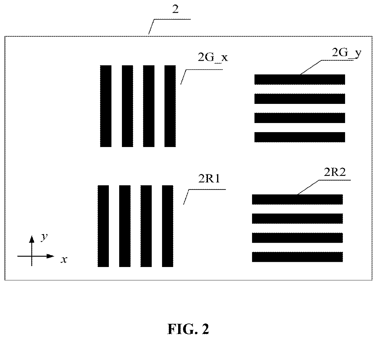
[0053]As shown in FIG. 2, the object plane marking plate 2 in the present invention comprises a pair of object plane wave aberration test gratings 2G_x and 2G_y with the shear diffraction directions being X direction and Y direction respectively, and a pair of object plane light intensity test marks 2R1 and 2R2; the object plane wave aberration test gratings 2G_x, 2G_y and the object plane light intensity test marks 2R1 and 2R2 are positioned in the object side field-of-view and uniformly illuminated by the light source and illumination system 1, and the illumination numerical aperture fills the object numerical aperture range of the tested projection objective 4 to be measured; the distance between the object plane wave aberration test grating pair 2G_x and 2G_y is equal to the distance between the object plane light intensity test mark pair 2R1 and 2R2; the object plane light intensity test marks 2R1 and 2R2 are gratings.

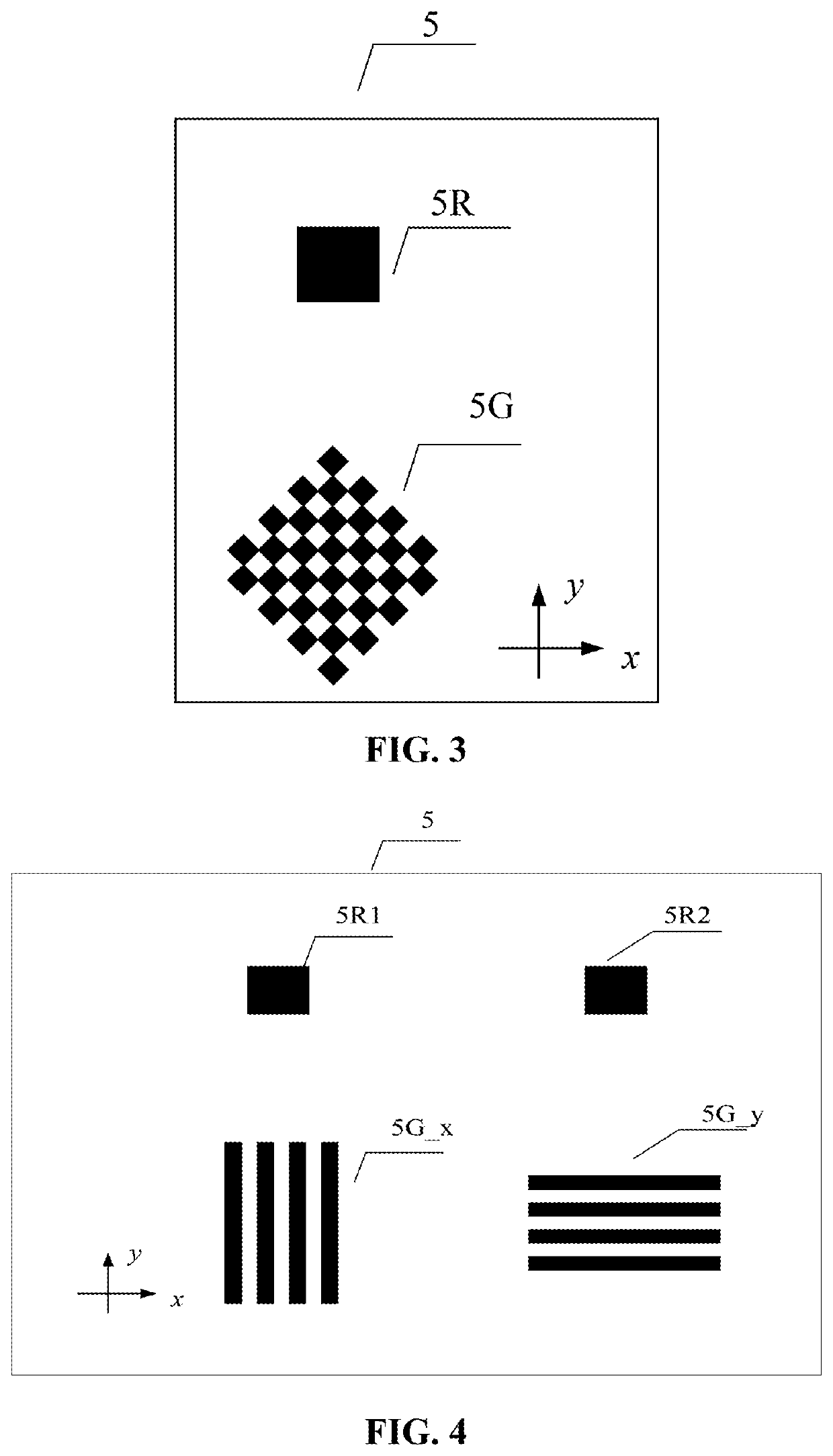
[0054]As shown in FIG. 3, the first embodiment of the image ...

second embodiment

[0055]As shown in FIG. 4, the image plane marking plate 5 of the present invention comprises a set of image plane shear gratings 5G_x and 5G_y matched with the object plane wave aberration test gratings 2G_x and 2G_y in FIG. 2, and image plane light passing holes 5R1 and 5R2 matched with the object plane light intensity test marks 2R1 and 2R2; the image plane shear gratings 5G_x, 5G_y are two orthogonal one-dimensional gratings, with the shear diffraction direction of the image plane shear grating 5G_x being the X direction, and the shear diffraction direction of the image plane shear grating 5G_y being the Y direction; the object plane wave aberration test grating, the object plane light intensity test marks, the image plane shear grating and the image plane light passing hole are used as a set; the distance between the object plane wave aberration test grating 2G_x and the object plane light intensity test mark 2R1 and the distance between the image plane shear grating 5G_x and th...

third embodiment

[0058]As shown in FIG. 7, the image plane marking plate 5 of the present invention comprises two sets of image plane shear gratings 5G1, 5G2 mated with the object plane wave aberration test gratings 2G1_x, 2G1_y, 2G2_x, and 2G2_y in FIG. 6 and image plane light passing hole 5R used in conjunction with object plane light intensity test marks 2R1, 2R2; the image plane shear gratings 5G1 and 5G2 are two-dimensional checkerboard gratings, and its shear diffraction directions are the X direction and the Y direction; As the object plane displacement table 3 and the image plane displacement table 7 are moved, the object plane wave aberration test grating 2G1_x and 2G2_x and one object plane light intensity test mark 2R1 in the X direction can be respectively imaged to positions of the image plane shear grating 5G1 and 5G2 and the image plane light passing hole 5R through the tested projection objective 4, and the object plane wave aberration test grating 2G1_y and 2G2_y and another object ...


PUM


Abstract

A light intensity fluctuation-insensitive projection objective wave aberration detection device and a detection method thereof, comprising a light source and illumination system, an object plane marking plate, an object plane displacement table, a tested projection objective, an image plane marking plate, a two-dimensional photosensor, an image plane displacement table and a control processing unit; the object plane marking plate and the image plane marking plate are provided with grating marks for shear interference test and marks for light intensity test, the shear interferograms and the light intensity information are simultaneously received through the two-dimensional photosensor, the light intensity fluctuation error corresponding to each phase-shifting interferogram is corrected through the light intensity information, improving the detection precision, reducing the complexity and the cost of the system, and improving the detection speed.

Description

CROSS-REFERENCE TO RELATED APPLICATIONS[0001]The subject application claims priority on Chinese Application No. CN202010000986.8 filed on Jan. 2, 2020 in China. The contents and subject matter of the Chinese priority application is incorporated herein by reference.TECHNICAL FIELD[0002]The present invention relates to a lithography machine, in particular, a projection objective wave aberration detection device that is insensitive to light intensity fluctuation and a detection method thereof.BACKGROUND ART[0003]The Ronchi grating shear interferometer has the advantages of common optical path, no space optical path difference, no need of an independent ideal reference wave surface, high precision, high sensitivity, and simple structure, which is effective to measure wave aberration of an optical system. Especially for high-end projection lithography machine, the shear interferometer is one of the main technical solutions for in-situ and off-line wave aberration detection for projection...

Claims


Application Information

Patent Timeline
IPC IPC(8): G01J9/02G03F7/20G01M11/02
CPCG01J9/0215G01M11/0271G03F7/706G01B9/02098
Inventor TANG, FENGWANG, XIANGZHAOLU, YUNJUNPENG, CHANGZHELIU, YANG
Owner SHANGHAI INST OF OPTICS & FINE MECHANICS CHINESE ACAD OF SCI
Why Eureka
Try Eureka