
Fast pulse, high current laser drivers

a laser driver and high current technology, applied in the field of pulsed laser driver, can solve the problem that the conventional si mosfet based laser driver circuit cannot deliver the required performan

Pending Publication Date: 2021-04-15
GAN SYST
View PDF0 Cites 24 Cited by
  • Summary
  • Abstract
  • Description
  • Claims
  • Application Information

AI Technical Summary

Benefits of technology

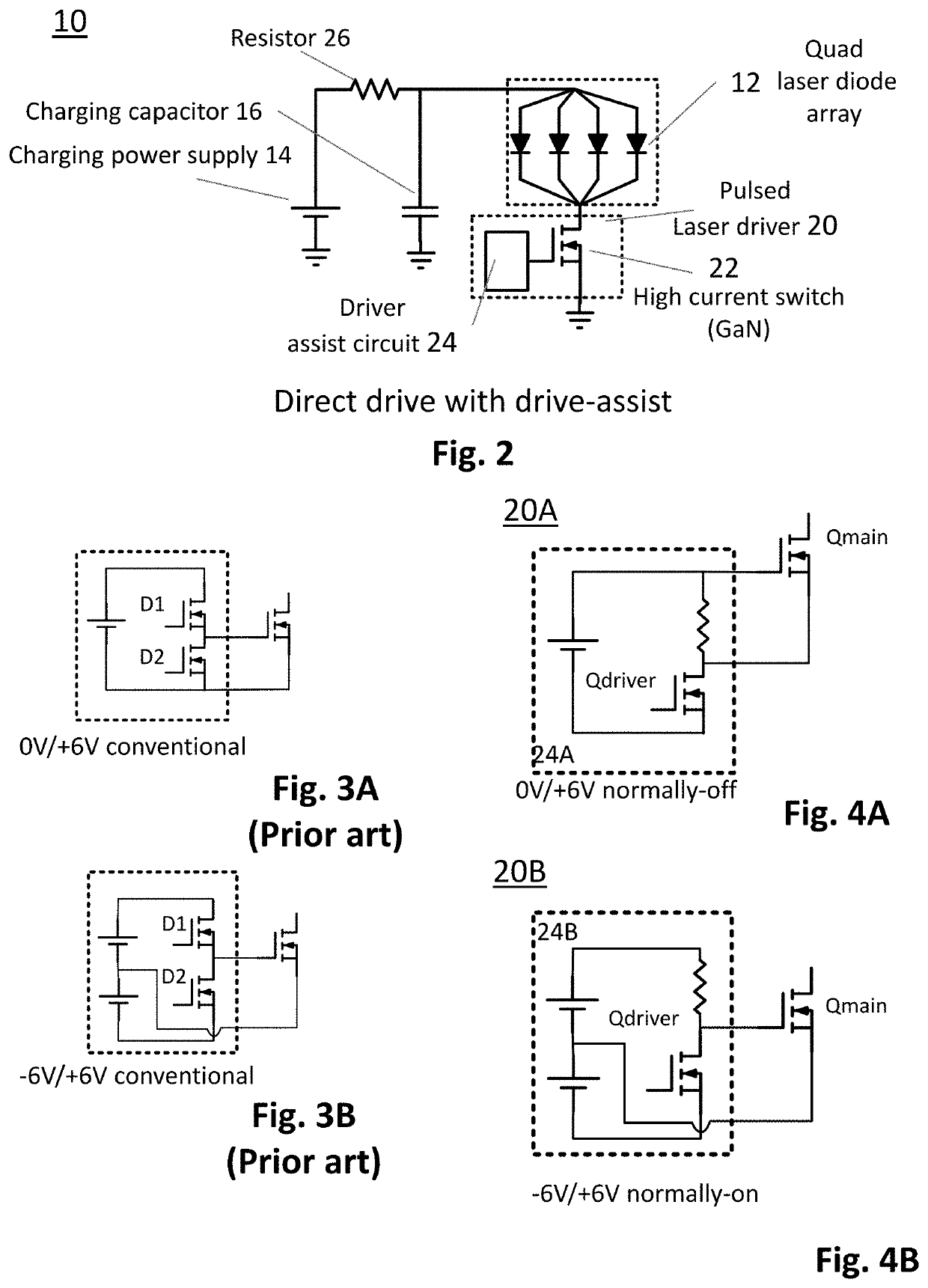
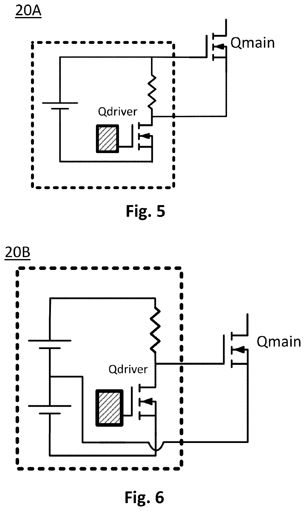
The present invention offers pulsed laser drivers for diode laser systems, such as those used in LIDAR systems. These drivers are designed to provide fast, high current switching, and can help overcome limitations of existing solutions. One driver is a direct drive laser driver with a fast high current transistor and a drain recovery circuit. This driver can generate a laser pulse with a high peak power and a short rise time. Another driver is a current switch with a normally-on transistor that triggers the laser pulse and then stays on for a while to recover energy and protect other components. These drivers can help improve the performance and reliability of diode laser systems.

Problems solved by technology

Conventional Si MOSFET based laser driver circuits cannot deliver the required performance, e.g. due to one or more of: slow transistors, low current drivers, high inductance layouts, and poor topology choices.

Method used


Image

  • Fast pulse, high current laser drivers
  • Fast pulse, high current laser drivers
  • Fast pulse, high current laser drivers

Examples


Embodiment Construction

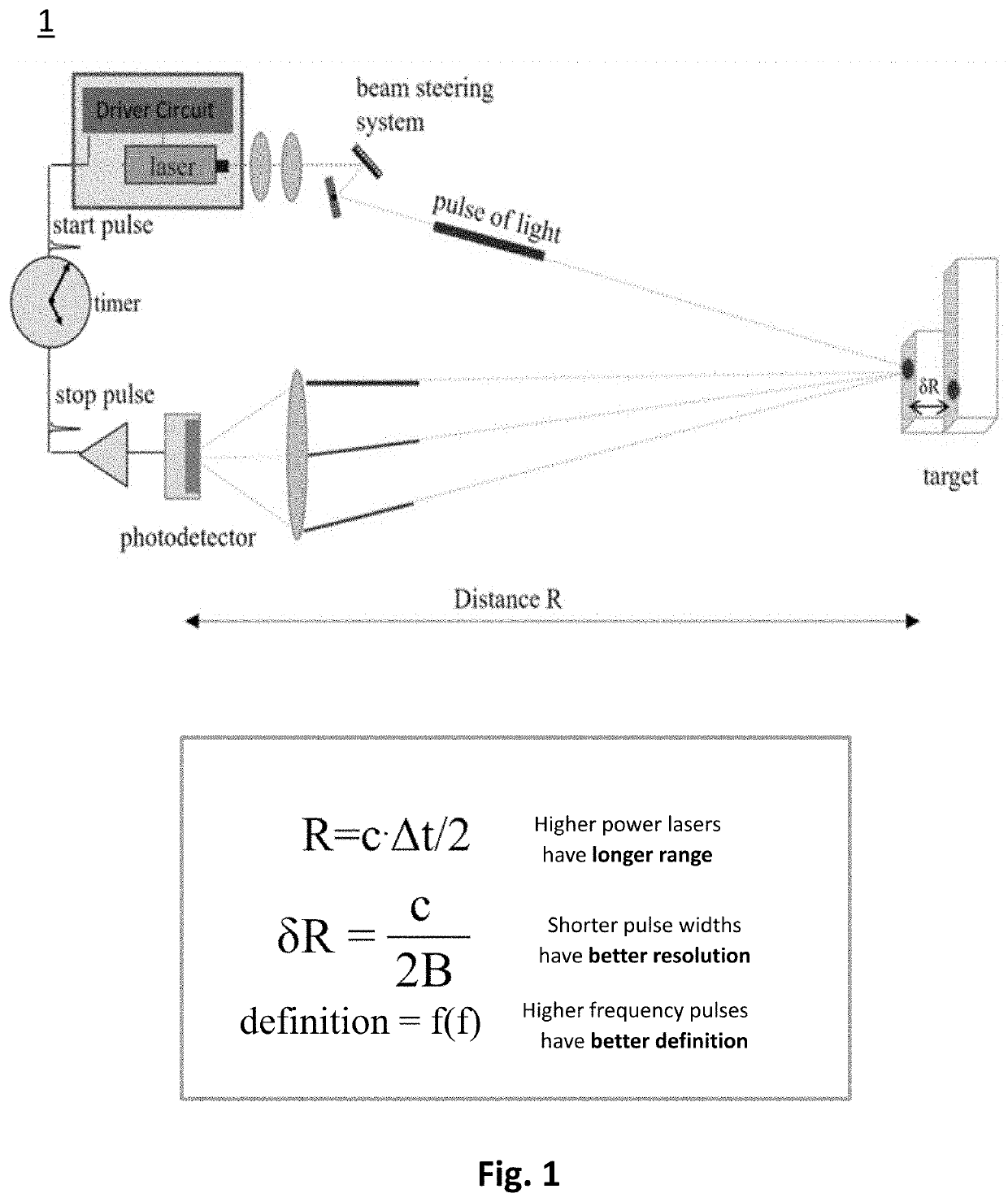
[0041]FIG. 1 shows a simplified schematic diagram of a LIDAR system 1. An explanation of the components and principle of operation of a LIDAR system of this type can be found, for example, in the above-mentioned patent and non-patent references.

[0042]In summary, the range R is determined from the time of flight Δt, the speed of light c as: R=c·Δt / 2 and δR=c / 2B.

[0043]Higher power lasers have longer range, and shorter laser pulse widths provide better resolution. Better definition is achieved for higher frequency pulses, i.e. for higher pulse repetition rate, which may be in the kHz to MHz range.

[0044]LIDAR systems for automotive applications, such as collision avoidance systems are typically based on diode lasers operating at 1000 nm, e.g. 1555 nm, are under development and may be preferred for eye safety, but at present these are not economically feasible.

[0045]Pulsed Laser Driver Circuit for Direct Drive with Drive Assist

[0046]A circuit schematic for a system 10 comprising a quad d...


PUM


Abstract

Pulsed laser drivers are disclosed comprising Gallium Nitride (GaN) power transistors for driving diode laser systems requiring high current and fast pulses, such as laser drivers for LIDAR (Light Detection and Ranging) systems. Drivers are capable of delivering pulses with peak current ≥100 A, e.g. 170 A to provide high peak power, fast pulses with nanosecond rise times and nanosecond pulse duration, for driving multi-channel laser diode arrays with 40 A per channel for 120 W output per channel for a combined peak output of 480 W. For lower duty cycle, example driver circuits are disclosed comprising a high current power transistor for direct drive with drive assist. For higher duty cycle, example resonant driver circuits are disclosed comprising two high current power transistors. Implementation of resonant driver circuits with GaN technology provides fast charging for short pulse operation at higher repetition rates or for pulse code modulation.

Description

CROSS-REFERENCE TO RELATED APPLICATION(S)[0001]This application claims priority from U.S. provisional patent application No. 62 / 281,484, filed Mar. 1, 2019, entitled “FAST PULSE, HIGH CURRENT LASER DRIVERS”, which is incorporated herein by reference, in its entirety.TECHNICAL FIELD[0002]The present invention relates to pulsed laser drivers and particularly to driver circuitry comprising Gallium Nitride (GaN) power transistors for driving diode laser systems requiring high current and fast pulses, such as laser drivers for LIDAR (Light Detection and Ranging) systems.BACKGROUND ART[0003]LIDAR systems employ pulses of light to measure distance to an object based on time of flight (ToF). Distance is computed based on the time elapsed between emission of a light pulse from a light source (emitter), such as a laser diode, and detection of a reflected pulse of light by a detector which is mounted near the emitter. Some systems use a single light emitter and detector with rotating mirrors t...

Claims


Application Information

Patent Timeline
IPC IPC(8): H01S5/042H01S5/40G01S7/484G01S17/10H03K3/012
CPCH01S5/0428H01S5/4025H03K3/012G01S17/10G01S7/484
Inventor MOUSAVIAN, HOSSEINSPAZIANI, LARRY
Owner GAN SYST
Learn More