Cleaning system and a method of cleaning

Active Publication Date: 2021-04-15
ROLLS ROYCE PLC
View PDF0 Cites 5 Cited by
  • Summary
  • Abstract
  • Description
  • Claims
  • Application Information

AI Technical Summary

Benefits of technology

The cleaning system and method described in the patent text may use a pump to create a low particulate size mist through an engine core, which may improve blade cleaning without the need for a starter motor. This may reduce the consumption of water and detergent, as well as any environmental impact associated with cleaning. The pump and tooling sealed to the rear of the engine core may improve collection efficiency and reduce contamination. The cleaning system may not require a specialist technician to operate the gas turbine engine and may lower operational costs and risks as the engine is not operational during cleaning. Cleaning may occur in situ while the engine is mounted on the aircraft or in a test cell or cleaned off-wing.

Problems solved by technology

The accumulation of this debris can detrimentally affect engine performance and efficiency and may cause wear, thus necessitating periodic cleaning and maintenance.
Cleaning a gas turbine engine, especially air passages within an engine core of the gas turbine engine, can be a difficult operation.
This is a time consuming and costly operation, requiring specialised equipment and specialist technicians and can present certain health and safety risks.
During the operation, which typically involves cleaning two or four engines, the engines and the aircraft are not available for use, which is very costly for the airline that owns or leases the aircraft.
Further, the starter motor can only be used for limited periods and require cooling before next use.
Also, such methods can lead to contamination of a cabin bleed.
Conventional methods also require large volumes of liquid that may be difficult to deliver, collect, remove and dispose.
This is beneficial as when using conventional engine cleaning methods, wash fluid can be pushed into cabin bleed and other engine systems, causing additional maintenance and sometimes leaving an unpleasant aroma within the cabin of the aircraft.
This may lower operational costs and reduce process time.

Method used


Image

  • Cleaning system and a method of cleaning
  • Cleaning system and a method of cleaning
  • Cleaning system and a method of cleaning

Examples


Embodiment Construction

[0063]Aspects and embodiments of the present disclosure will now be discussed with reference to the accompanying figures. Further aspects and embodiments will be apparent to those skilled in the art.

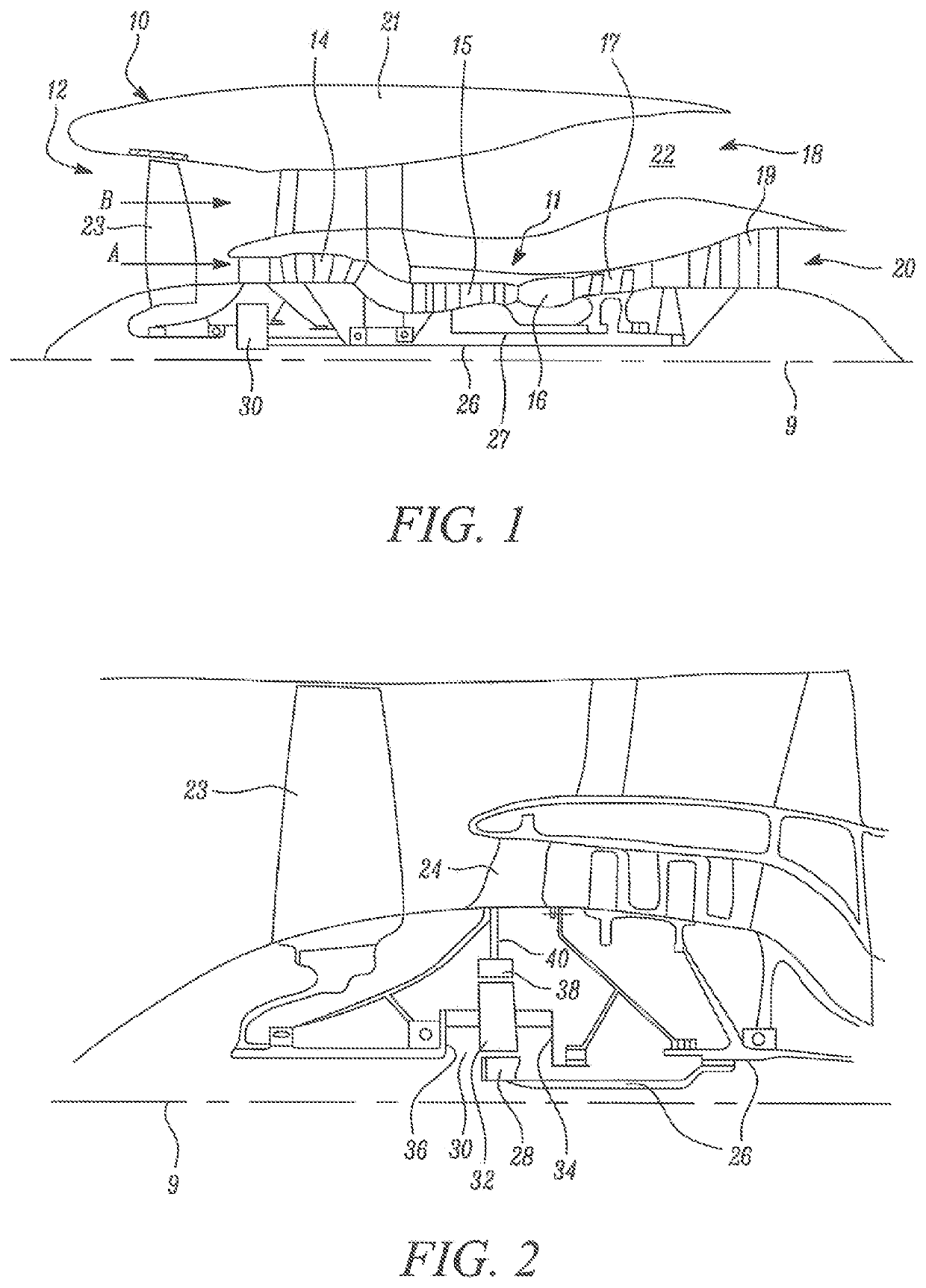
[0064]FIG. 1 illustrates a gas turbine engine 10 having a principal rotational axis 9. The engine 10 comprises an air intake 12 and a propulsive fan 23 that generates two airflows: a core airflow A and a bypass airflow B. The gas turbine engine 10 comprises a core 11 that receives the core airflow A. The engine core 11 comprises, in axial flow series, a low pressure compressor 14, a high pressure compressor 15, combustion equipment 16, a high pressure turbine 17, a low pressure turbine 19 and a core exhaust nozzle 20. A nacelle 21 surrounds the gas turbine engine 10 and defines a bypass duct 22 and a bypass exhaust nozzle 18. The bypass airflow B flows through the bypass duct 22. The fan 23 is attached to and driven by the low pressure turbine 19 via a shaft 26 and an epicyclic gearbox 3...


PUM


Abstract

A cleaning system for cleaning gas paths in an engine core of a gas turbine engine is provided. The cleaning system includes a source of an engine cleaning liquid; an engine cleaning mist forming unit that vapourises the engine cleaning liquid to form an engine cleaning mist and delivers the engine cleaning mist into the engine core of the gas turbine engine; at least one delivery device configured to deliver the engine cleaning liquid to the engine cleaning mist forming unit; a pump configured to draw the engine cleaning mist through the engine core to clean the gas paths within the engine core; and a mist collecting arrangement including a condensing chamber. The mist collecting arrangement is configured to collect the engine cleaning mist that has passed through the engine core and condense the collected engine cleaning mist in the condensing chamber.

Description

CROSS-REFERENCE TO RELATED APPLICATIONS[0001]This specification is based upon and claims the benefit of priority from UK Patent Application Number 1914723.0 filed on 11 Oct. 2019, which is hereby incorporated herein in its entirety.BACKGROUNDTechnical Field[0002]The present disclosure relates to a cleaning system for cleaning an engine core of a gas turbine engine and a method of cleaning an engine core of a gas turbine engine.Description of the Related Art[0003]Gas turbine engines, especially those powering an aircraft, ingest debris such as sand, dust, soot and carbon during use. The accumulation of this debris can detrimentally affect engine performance and efficiency and may cause wear, thus necessitating periodic cleaning and maintenance. Cleaning a gas turbine engine, especially air passages within an engine core of the gas turbine engine, can be a difficult operation. For gas turbine engines powering the aircraft, the cleaning can require temporarily removing the gas turbine ...

Claims


Application Information

Patent Timeline
IPC IPC(8): F01D25/00
CPCF01D25/002F05D2220/323F01D25/32F05D2230/72Y02T50/60
Inventor RIGG, GRAEME E.AGGAS, TIMOTHY P.MUNTON, DAVID
Owner ROLLS ROYCE PLC
Why Eureka
Try Eureka