
Exhaust gas treatment system with upstream scr catalyst

a technology of exhaust gas treatment and catalyst, which is applied in the direction of physical/chemical process catalysts, metal/metal-oxide/metal-hydroxide catalysts, machines/engines, etc., can solve the problems of greater challenges, achieve enhanced nox removal, reduce n2o emissions, and effectively treat exhaust gas

Active Publication Date: 2021-03-18
BASF CORP
View PDF0 Cites 11 Cited by
  • Summary
  • Abstract
  • Description
  • Claims
  • Application Information

AI Technical Summary

Benefits of technology

The present patent describes an exhaust gas treatment system that uses a series of catalysts to effectively remove nitrogen oxides (NOx) from exhaust gas. This system includes an upstream SCR catalyst that can enhance NOx removal and decrease N2O emissions compared to a system without this catalyst. The total NOx conversion across the system is greater than 95%, with brake specific NOx values of less than 0.1 g / bhph. The total N2O emissions across the system are with BSN2O values of less than 0.019 g / bhph. The patent also describes a method of treating an exhaust gas stream by contacting it with the system to reduce nitrogen oxides in the exhaust gas.

Problems solved by technology

One key problem for attaining high NOx reduction over selective catalytic reduction (SCR) catalysts is having adequate exhaust temperature for the SCR reaction.
In addition, engines using reduced exhaust gas recirculation (EGR) for better efficiency experience increased engine-out NOx levels, making it even a greater challenge to meet the current target values.
Another challenge for certain HDD systems relates to meeting N2O limits, as N2O is a typical byproduct of the SCR reaction.
Since these exhaust characteristics create challenges for current diesel emission catalyst technology, there remains a need in the art for new catalyst systems that meet increasingly stringent environmental regulations.

Method used


Image

  • Exhaust gas treatment system with upstream scr catalyst
  • Exhaust gas treatment system with upstream scr catalyst
  • Exhaust gas treatment system with upstream scr catalyst

Examples


example 1

System

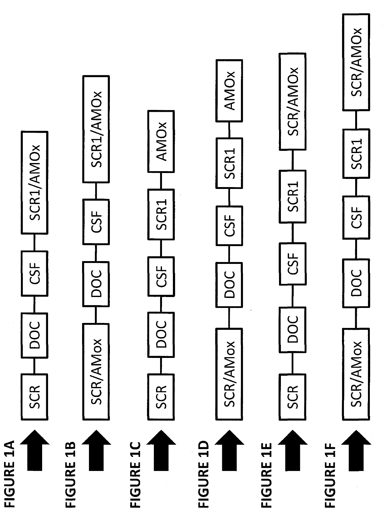
[0153]A standard exhaust system was prepared with the general structure shown in FIG. 5A, having a close-coupled DOC, followed by a downstream CSF, a downstream SCR (“SCR1”) catalyst, and a downstream SCR / AMOx catalyst. The DOC was a flow-thru DOC coated onto a 13″×6″ flow-thru substrate with 400 cpsi and 4 mil wall thickness. It was formulated with Pt and Pd on alumina. The DOC was zoned, with an inlet zone that was 33% of the total catalyst length (i.e., 2″) and designed for fuel L / O function for active regeneration. The DOC had a 60 g / ft3 Pt and Pd at a 1:1 ratio. The rear zone 67% of the catalyst length (i.e. 4″) was for oxidizing NO to NO2 and had 30 g / ft3 Pt and Pd at 5:1 ratio. The overall platinum-group metal loading on this DOC was 40 g / ft3 (2:1 ratio). The CSF was a 13″×7″ filter substrate with 300 cpsi and a 9 mil wall thickness. The filter substrate was coated with 4 g / ft3 Pt and Pd at 4:1 ratio supported on alumina. The SCR1 catalyst contained a Fe / Cu-CHA zoned SC...

example 2

System A

[0156]An exhaust system was prepared with the general structure shown in FIG. 5B, with a close-coupled SCR (cc-SCR) upstream of the other components of the system, having a close-coupled SCR, followed by a downstream DOC, followed by a downstream CSF, a downstream SCR (“SCR1”) catalyst, and a downstream SCR / AMOx catalyst. The cc-SCR for this analysis was not truly close-coupled, but was located downstream of the engine by about 8.5 feet from turbo-out for access purposes. Nonetheless, the cc-SCR was positioned so as to take advantage of the higher temperatures in a location nearer to engine-out. This system also required dual urea injection (one injection upstream of the cc-SCR and one injection upstream of SCR-1).

[0157]The cc-SCR used in this testing was a zoned SCR / AMOx catalyst, coated onto a 10.5″×9″ / 600 / 4.5HP substrate. The catalyst had a 3″ outlet AMOx zone with a 2 g / ft3 Pt-only bottom coat. The full length top coat comprised Cu-CHA (3.25% CuO) and had a DG of 2.75 g / ...

example 3

[0177]A study was conducted to compare the effect of the specific upstream SCR composition in the exhaust gas treatment system, and in particular, to an exhaust gas treatment system comprising the following configuration: SCR / AMOx-DOC-CSF-SCR-AMOx.

[0178]A first, comparative system was provided, under fresh conditions, comprising an SCR / AMOX upstream of a standard Euro VI or US EPA 2010 aftertreatment system of DOC / CSF / SCR / AMOX. It is known that SO3 (rather than SO2) acts as a deactivation species, especially for zeolite-based SCR materials. The fraction of SO3 entering the upstream SCR is significantly less than for the downstream SCR as it does not contain an oxidation catalyst upstream of it; however, the engine will, under normal operating conditions, still emit low concentrations of SO3. Deactivation of an upstream Cu-zeolite based SCR therefore commonly occurs over time, albeit at a slower rate compared to a downstream Cu-zeolite SCR.

[0179]The disadvantages of a system with an ...


PUM

PropertyMeasurementUnit
temperaturesaaaaaaaaaa
pore sizesaaaaaaaaaa
molar ratiosaaaaaaaaaa

Abstract

A system for treatment of an exhaust gas stream from an engine is provided, containing an upstream selective catalytic reduction (SCR) catalyst, which receives the exhaust gas stream without any intervening catalyst, a diesel oxidation catalyst (DOC) positioned downstream thereof; a catalyzed soot filter (CSF) downstream of the diesel oxidation catalyst; a second SCR catalyst positioned downstream of the catalyzed soot filter; and an ammonia oxidation (AMOx) catalyst. The application also describes use of such systems to reduce nitrogen oxides (NOx) and hydrocarbons (HC) in an exhaust gas stream.

Description

FIELD OF THE INVENTION[0001]The present invention relates to exhaust gas treatment systems comprising at least one catalyst article, and methods of use thereof.BACKGROUND OF THE INVENTION[0002]Emissions of diesel engines include particulate matter (PM), nitrogen oxides (NOx), unburned hydrocarbons (HC), and carbon monoxide (CO). NOx is a term used to describe various chemical species of nitrogen oxides, including nitrogen monoxide (NO) and nitrogen dioxide (NO2), among others. One key problem for attaining high NOx reduction over selective catalytic reduction (SCR) catalysts is having adequate exhaust temperature for the SCR reaction. In particular, this is often a concern for heavy duty diesel (HDD) on-road aftertreatment systems, wherein the SCR catalyst is positioned downstream of other catalysts (typically including a diesel oxidation catalyst (DOC) and catalyzed soot filter (CSF)). With such system configurations, the SCR experiences somewhat low temperature conditions, which c...

Claims


Application Information

Patent Timeline
Patent Type & Authority Applications(United States)
IPC IPC(8): F01N3/20B01J23/56B01J29/72F01N3/035F01N3/10
CPCF01N3/2066B01J23/56B01J29/723B01J2229/18F01N3/105F01N2250/12F01N2610/02F01N3/035F01N3/103F01N13/009F01N2510/0682F01N2510/0684F01N2510/02Y02T10/12F01N13/0093F01N2570/18F01N3/106F01N2610/1453
Inventor VOSS, KENNETH E.HALLSTROM, KEVIN A.SHAH, SANDIP D.YOUNGREN, DAVID M.THOMS, ANDREWKAZI, M. SHAHJAHANDORNER, ROBERT
Owner BASF CORP
Learn More