
Intravascular devices and fibrosis-inducing agents

a technology of intravascular devices and fibrosis, which is applied in the direction of blood vessels, prostheses, peptide/protein ingredients, etc., can solve the problems of perigraft leakage, device migration within the vessel or tissue, and inability to effectively attach the device to the surrounding tissue, etc., to achieve the effect of reducing perigraft leakag

Inactive Publication Date: 2005-07-07
ANGIOTECH INT AG (CH)
View PDF99 Cites 187 Cited by
  • Summary
  • Abstract
  • Description
  • Claims
  • Application Information

AI Technical Summary

Benefits of technology

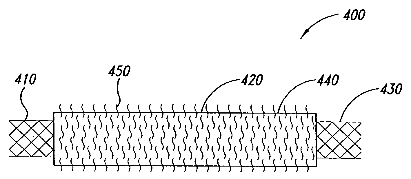
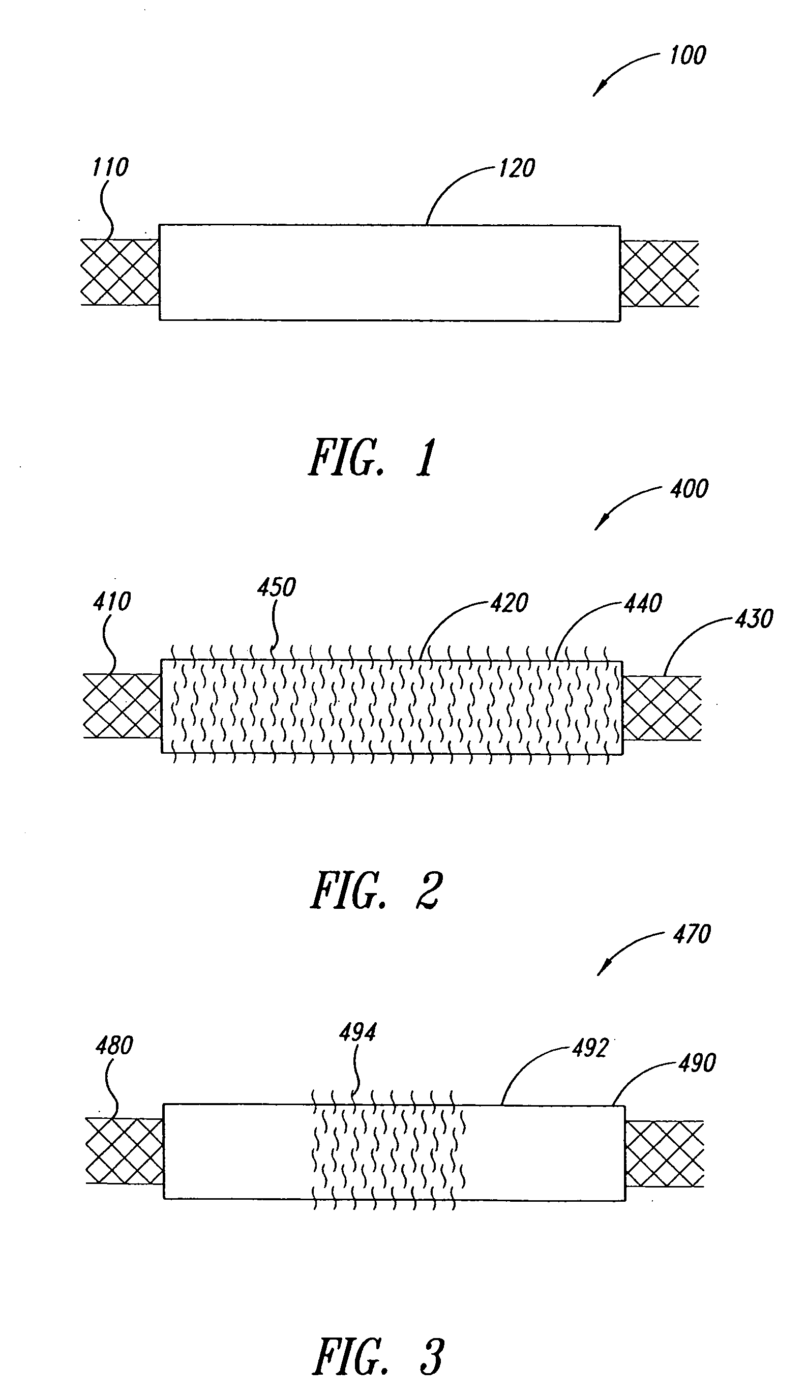
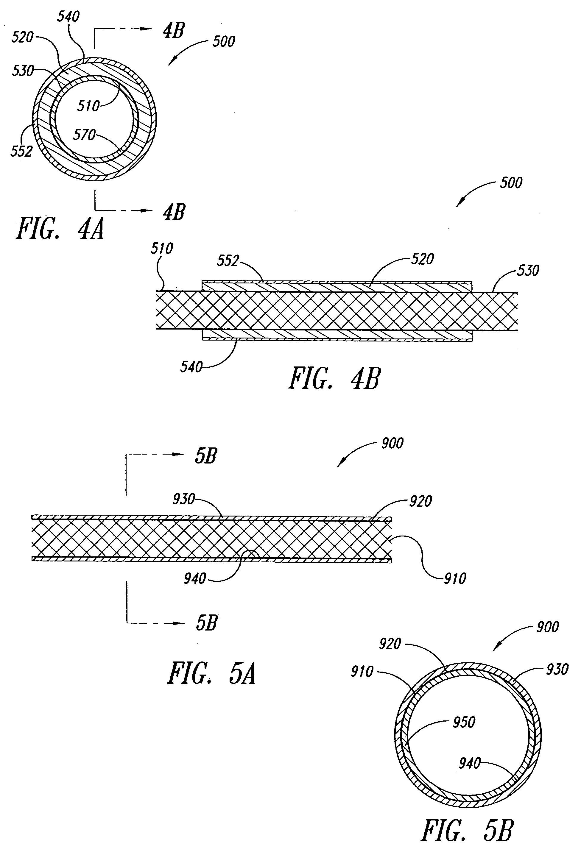
[0010] Briefly stated, the present invention provides compositions for delivery of selected therapeutic agents via intravascular devices, as well as methods for making and using these devices. Within one aspect of the invention, drug-coated or drug-impregnated stent grafts and aneurysm coils are provided which induce adhesion or fibrosis in the surrounding tissue, or facilitate “anchoring” of the device / implant in situ, thus enhancing the efficacy. In other aspects, compositions that include fibrosis-inducing agents for use in embolizing and / or occluding aneurysms are described. Within various embodiments, fibrosis is induced by local or systemic release of specific pharmacological agents that become localized to the adjacent tissue.
[0015] In another aspect, the present invention provides a method of reducing perigraft leakage associated with device delivery in a patient, comprising delivering a device to a patient, the device comprising a stent graft, and a fibrosing agent or a composition comprising a fibrosing agent, wherein the fibrosing agent induces a fibrotic response between the device and a patient in which the device is implanted.
[0016] In another aspect, the present invention provides a method of adhering a device in a patient with a cerebral aneurysm, comprising inserting the device into the patient, the device comprising an aneurysm coil or embolic agent, and a fibrosing agent or a composition comprising a fibrosing agent, wherein the fibrosing agent induces a fibrotic response between the device and a patient in which the device is implanted, thereby reducing the possibility of recanalization, re-establishment of blood flow, and ultimately disease recurrence.
[0018] In another aspect, the present invention provides a method comprising introducing into an aneurysm of a patient in need thereof, a therapeutically effective amount of a fibrosing agent or a composition comprising a fibrosing agent, where the fibrosing agent induces a fibrotic response at the aneurysm of the patient, thereby providing the patient with a beneficial result.
[0024] Also provided by the present invention are methods for treating patients having unstable plaque (e.g., coronary or peripheral vascular disease, atherosclerosis in saphenous vein grafts) using minimally invasive therapies (catheters, balloons, stents, other intravascular devices, pericardial drug delivery) as well as surgical treatment of a diseased portion of a vessel (i.e., bypass surgery, endarterectomy, or other surgical treatments of atherosclerosis) such that sites of vulnerable plaque are effectively treated. As utilized herein, it should be understood that “reduction in the risk of unstable plaque rupture” or “prevention / reduction in the incidence of infarction” refers to a statistically significant reduction in the, number, timing, or, rate of rupture of unstable plaque, which may or may not result in a permanent prohibition of any plaque rupture.

Problems solved by technology

Effective attachment of the device into the surrounding tissue, however, is not always readily achieved.
One reason for ineffective attachment is that implantable medical devices generally are composed of materials that are highly biocompatible and designed to reduce the host tissue response.
These materials (e.g., stainless steel, titanium based alloys, fluoropolymers, and ceramics) typically do not provide a good substrate for host tissue attachment and ingrowth during the scarring process.
As a result of poor attachment between the device and the host tissue, devices can have a tendency to migrate within the vessel or tissue in which they are implanted.
Device migration can result in device failure and, depending on the type and location of the device, can lead to leakage, aneurysm rupture, vessel occlusion, infarction, and / or damage to the surrounding tissue.
A disadvantage of mechanical fasteners, however, is that they can damage the tissue or vessel wall when the device is deployed and may not form a seal between the neck of the graft and the vessel wall.
The above-described modifications, however, have failed to provide a satisfactory long-term solution to the problem of device migration.

Method used


Image

  • Intravascular devices and fibrosis-inducing agents
  • Intravascular devices and fibrosis-inducing agents
  • Intravascular devices and fibrosis-inducing agents

Examples


example 1

Coating of Stents with Fibronectin

[2135] The coating apparatus consisted of an overhead stirrer (Fisher Scientific) orientated horizontally. A conical stainless steel head was attached to the revolving chuck of the stirrer. One end of the covered stent was pulled up onto the conical head until held firmly. The other end was attached to a clip-swivel device that held the covered stent in a horizontal position, but allowed the covered stent to rotate along its axis. The stirrer was then set to rotate at 30 rpm so that the whole covered stent rotated along the horizontal axis at this speed. A 1% (w / w) fibronectin (Calbiochem Corporation, San Diego, Calif.) solution in sterile water was prepared. Two hundred microlitres of this solution was slowly pipetted as a 3 mm wide ring located 5 mm from the end of the covered stent fixed in the conical steel head over a period of 2 minutes as the covered stent rotated. The fibronectin was then dried under a stream of nitrogen as the covered sten...

example 2

Coating of a Covered Stent with Poly-L-Lysine

[2136] The coating apparatus consisted of a Fisher overhead stirrer orientated horizontally. A conical stainless steel head was attached to the revolving chuck of the stirrer. One end of the covered stent was pulled up onto the conical head until held firmly. The other end was attached to a clip-swivel device that held the covered stent in a horizontal position, but allowed the covered stent covered stent to rotate along its axis. The stirrer was set to rotate at 30 rpm so that the whole covered stent rotated along the horizontal axis at this speed. A 1% (w / w) poly-L-Lysine (Sigma, St. Louis, Mo.) solution in sterile water was prepared. Two hundred microliters of this solution was slowly pipetted as a 3 mm wide ring located 5 mm from the end of the covered stent fixed in the conical steel head over a period of 2 minutes as the covered stent rotated. The poly-L-Lysine was then dried under a stream of nitrogen as the covered stent continue...

example 3

Coating of Covered Stents with N-Carboxybutyl Chitosan

[2137] The coating apparatus consists of a Fisher overhead stirrer orientated horizontally. A conical stainless steel head is attached to the revolving chuck of the stirrer. One end of the covered stent is pulled up onto the conical head until held firmly. The other end is attached to a clip-swivel device that holds the covered stent in a horizontal position, but allows the covered stent to rotate along its axis. The stirrer is set to rotate at 30 rpm so that the whole covered stent rotates along the horizontal axis at this speed. A 1% (w / w) n-carboxybutyl chitosan (Carbomer, Westborough, Mass.) solution in sterile water is prepared. Two hundred microlitres of this solution is slowly pipetted as a 3 mm wide ring located 5 mm from the end of the covered stent fixed in the conical steel head over a period of 2 minutes as the covered stent rotates. The n-carboxybutyl chitosan is dried under a stream of nitrogen as the covered stent...


PUM

PropertyMeasurementUnit
Fractionaaaaaaaaaa
Fractionaaaaaaaaaa
Fractionaaaaaaaaaa

Abstract

Intravascular devices (e.g., stents, stent grafts, covered stents, aneurysm coils, embolic agents and drug delivery catheters and balloons) are used in combination with fibrosing agents in order to induce fibrosis that may otherwise not occur when the implant is placed within an animal or to promote fibrosis betweent the devices and the host tissues. Compositions and methods are described for use in the treatment of aneurysms and unstable arterial (vulnerable) plaque.

Description

CROSS REFERENCE TO RELATED APPLICATIONS [0001] This application is a Continuation of U.S. Utility application Ser. No. 10 / 986,450, filed Nov. 10, 2004; which claims the benefit under 35 USC 119(e) of U.S. Provisional Application Ser. No. 60 / 518,785, filed Nov. 10, 2003; U.S. Provisional Application Ser. No. 60 / 523,908, filed Nov. 20, 2003; U.S. Provisional Application Ser. No. 60 / 524,023, filed Nov. 20, 2003; U.S. Provisional Application Ser. No. 60 / 582,833, filed Jun. 24, 2004; U.S. Provisional Application Ser. No. 60 / 586,861, filed Jul. 9, 2004; and U.S. Provisional Application Ser. No. 60 / 578,471, filed Jun. 9, 2004, which applications are incorporated herein by reference in their entireties.BACKGROUND OF THE INVENTION [0002] 1. Field of the Invention [0003] The present invention relates generally to pharmaceutical agents and compositions, drug-coated vascular implants, arterial drug-delivery devices, and more specifically, to compositions and methods for preparing vascular impla...

Claims


Application Information

Patent Timeline
IPC IPC(8): A61B17/00A61B17/11A61B17/12A61F2/00A61F2/86A61F13/00A61K38/48A61L27/00A61L27/54A61L31/00A61L31/16A61M29/00A61M31/00
CPCA61B17/00491A61L2300/412A61B17/12022A61B17/12045A61B17/12136A61B17/1215A61B17/12172A61B17/12177A61B17/12186A61B17/1219A61B2017/00004A61F2/86A61F2250/0067A61L31/16A61B17/11
Inventor HUNTER, WILLIAM L.GRAVETT, DAVID M.TOLEIKIS, PHILIP M.MAITI, ARPITASIGNORE, PIERRE E.LIGGINS, RICHARD T.GUAN, DECHI
Owner ANGIOTECH INT AG (CH)
Learn More