
Joint connection method for long pipe, and method for producing coiled tubing with joints

Pending Publication Date: 2021-02-04
NIPPON STEEL CORP
View PDF0 Cites 2 Cited by
  • Summary
  • Abstract
  • Description
  • Claims
  • Application Information

AI Technical Summary

Benefits of technology

The joint connection method described in this patent allows for the proper connection of joints to long pipes, which can be used for conducting hydraulic pressure tests and other procedures. Additionally, the patent describes a method for producing coiled tubing with joints. Essentially, this patent provides techniques for effectively connecting hydraulic components to long pipes and producing a reliable and usable product.

Problems solved by technology

However, because in some cases the cross section of a long pipe is not a perfect circle, when a collet chuck-type joint is used there is a risk that a gap will arise between the joint and the outer surface of the long pipe.
Therefore, there is a risk that a water leak may occur from the aforementioned gap, and an appropriate hydraulic pressure test will not be performed.
However, it is difficult to perform X-ray inspection of a weld zone of a welded joint after being wound around a reel, and whether or not an appropriate girth weld zone is formed so that a water leakage does not occur cannot be adequately confirmed.
The above described problem is not necessarily limited to the case of subjecting a long pipe to a hydraulic pressure test, and it is a problem that is common to cases where water is fed into the inside of a long pipe through a joint connected to an end portion of the long pipe, such as in the case of washing the inside of a long pipe.

Method used


Image

  • Joint connection method for long pipe, and method for producing coiled tubing with joints
  • Joint connection method for long pipe, and method for producing coiled tubing with joints
  • Joint connection method for long pipe, and method for producing coiled tubing with joints

Examples


Embodiment Construction

[0038]Embodiments of the present invention are described hereunder. Note that, although embodiments of the present invention are described by way of examples in the following description, the present invention is not limited to the examples described hereunder.

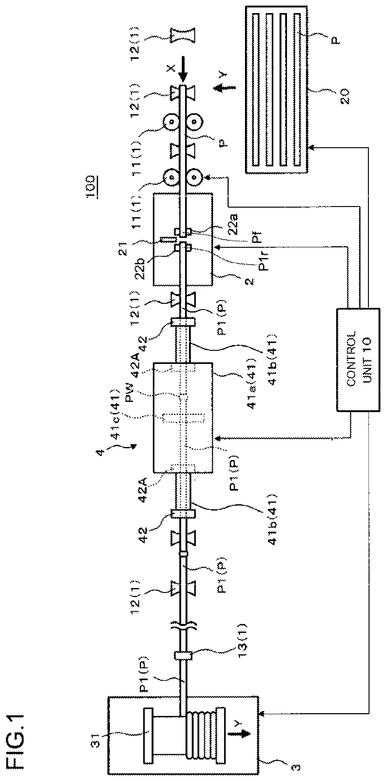
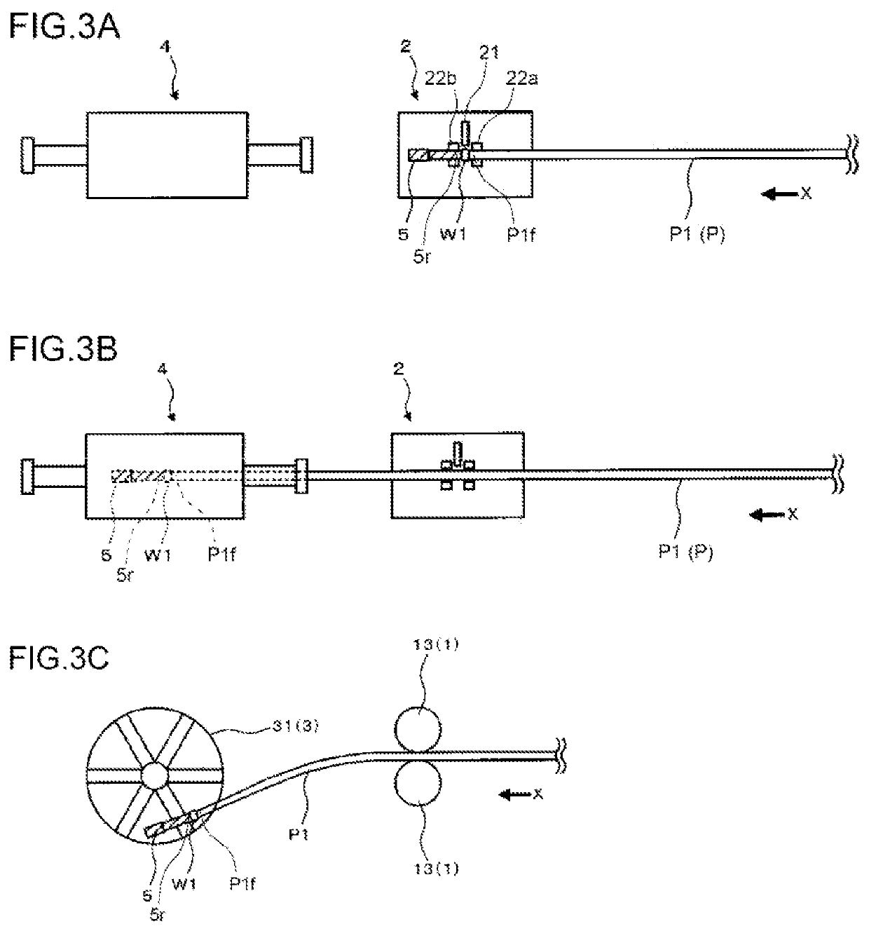
[0039]As the result of conducting intensive studies with a view to solving the problem described above, the present inventors focused their attention on utilizing a production facility for a long pipe capable of conducting an X-ray inspection of a girth weld zone of a long pipe as described in Patent Literature 2. Specifically, a welding apparatus included in the production facility for a long pipe is an apparatus whose original purpose is to be used for performing girth welding of end portions of a plurality of pipes to weld the end portions together to form a long pipe. The present inventors had the idea of diverting the welding apparatus for use also in the case of girth welding a joint to an end portion of a long pipe. Fur...


PUM


Abstract

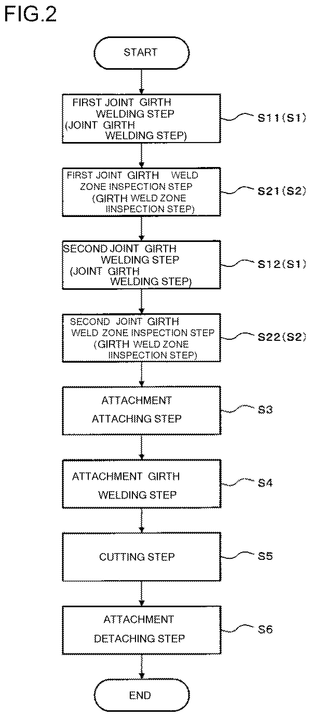
A joint connection method is provided that is a method for connecting joints that are used for a hydraulic pressure test or the like to a long pipe by using a production facility which includes a conveyance system, a welding apparatus, a winding apparatus and an X-ray inspection apparatus. The joint connection method includes a step of girth welding a first joint to a front end portion of the long pipe by means of the welding apparatus, a step of inspecting a girth weld zone of the first joint by means of the X-ray inspection apparatus, a step of girth welding a second joint to a rear end portion of the long pipe by means of the welding apparatus, and a step of inspecting a girth weld zone of the second joint by means of the X-ray inspection apparatus.

Description

TECHNICAL FIELD[0001]The present invention relates to a joint connection method for a long pipe, which can appropriately connect joints to be used for conducting a hydraulic pressure test or the like to end portions of a long pipe. In the present description, a long pipe is a pipe which is formed by performing girth welding to weld together end portions of a plurality of pipes, and is to be wound around a reel. The present invention also relates to a method for producing coiled tubing with joints that utilizes the joint connection method.BACKGROUND ART[0002]As disclosed in International Application Publication No. WO199831499 (Patent Literature 1), a pipe wound around a reel that is referred to as “coiled tubing” is already known. The coiled tubing is, for example, unwound from the reel on the sea and is let down into a well of an offshore oil field or offshore gas field or the like. The coiled tubing is, for example, utilized as an umbilical tube that accommodates an umbilical cabl...

Claims


Application Information

Patent Timeline
IPC IPC(8): F16L47/02B23K9/235B23K31/12
CPCF16L47/02B23K2101/06B23K31/125B23K9/235G01N2223/628G01N2223/629B23K37/053
Inventor TSUTO, AKIRAKAITANI, HIROYUKI
Owner NIPPON STEEL CORP
Learn More