Eureka AIR delivers breakthrough ideas for toughest innovation challenges, trusted by R&D personnel around the world.

Vehicle drive device

Pending Publication Date: 2022-08-25
TOYOTA JIDOSHA KK
View PDF0 Cites 0 Cited by
  • Summary
  • Abstract
  • Description
  • Claims
  • Application Information

AI Technical Summary

Benefits of technology

The vehicle drive device described in the patent allows for switching between a two-wheel drive mode and a four-wheel drive mode using a differential mechanism with a disconnection-connection mechanism. The issue addressed in this patent is that when switching from the two-wheel drive mode to the four-wheel drive mode, the other output shaft cannot be appropriately connected to the third rotating element by the disconnection-connection mechanism. This patent achieves a solution to allow for appropriate connection between the other output shaft and the third rotating element in the four-wheel drive mode.

Problems solved by technology

However, in this case, there is an issue that when the second traveling mode is switched to the first traveling mode, the other output shaft cannot be appropriately connected to the third rotating element by the disconnection-connection mechanism because there is a rotational speed difference between the third rotating element and the other output shaft.

Method used


Image

  • Vehicle drive device
  • Vehicle drive device
  • Vehicle drive device

Examples


first embodiment

[0038]A first embodiment of a vehicle drive device according to the present disclosure will be described below. Note that, an applicable embodiment of the present disclosure is not limited to the present embodiment.

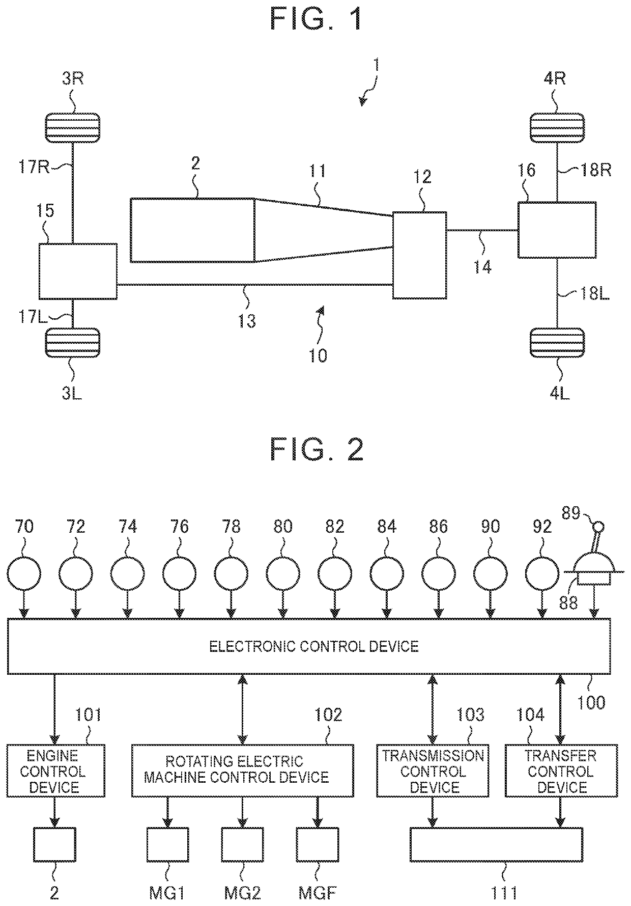
[0039]FIG. 1 is a diagram showing a schematic configuration of a vehicle 1 provided with a drive device 10 according to the first embodiment. The vehicle 1 includes right and left front wheels 3R, 3L, right and left rear wheels 4R, 4L, and the drive device 10 that transfers power from an engine 2 as a first power source to the right and left front wheels 3R, 3L and the right and left rear wheels 4R, 4L. This vehicle 1 is a four-wheel drive vehicle based on front-engine, rear-wheel-drive layout.

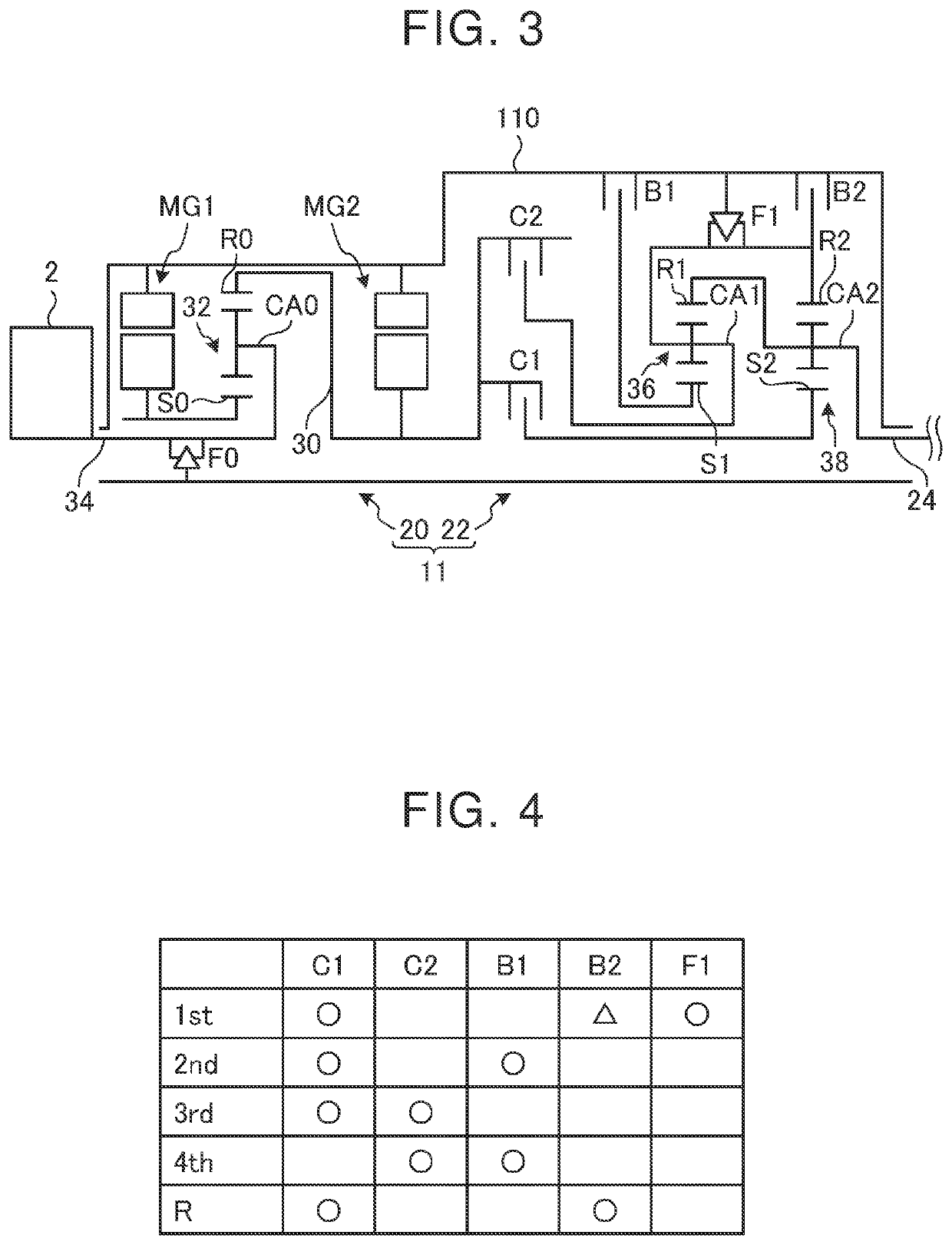
[0040]The drive device 10 includes the engine 2, a compound transmission 11 connected to the engine 2, a transfer 12 that is a front-rear wheel power distribution device connected to the compound transmission 11, and a front propeller shaft 13 and a rear propeller shaft 14 that are ...

second embodiment

[0110]Next, the vehicle 1 provided with the drive device 10 according to a second embodiment will be described. In the description of the second embodiment, reference signs are assigned for the same configuration as that of the first embodiment, and the description thereof will be omitted as appropriate.

[0111]FIG. 17 is a skeleton diagram schematically showing the transfer 12 according to the second embodiment, and is a skeleton diagram showing a case where the transfer 12 is in the first drive state. In the transfer 12 according to the second embodiment, the carrier CA3 of the third planetary gear device 64 is constantly connected to the rear wheel side output shaft 63 so as to rotate integrally with the rear wheel side output shaft 63.

[0112]The transfer 12 includes the connection switching device 40 (first dog clutch D1 and second dog clutch D2), the brake BF1, and the clutch CF1.

[0113]The transfer 12 according to the second embodiment includes the transfer member 65 that function...


PUM


Abstract

In a vehicle drive device, a second power source is connected to a first rotating element of a differential mechanism. The other output shaft of a first output shaft and a second output shaft is connected to a third rotating element so as to be disconnectable and connectable by a disconnection-connection mechanism. A control device places the disconnection-connection mechanism in a disconnected state. When a second traveling mode in which the third rotating element is fixed to a fixing member through engagement of a first engaging element is switched to a first traveling mode in which the disconnection-connection mechanism is placed in a connected state, the control device disengages the first engaging element, executes synchronous control in which rotational speeds of the other output shaft and the third rotating element are synchronized by a second engaging element, and switches the disconnection-connection mechanism from the disconnected state to the connected state.

Description

CROSS-REFERENCE TO RELATED APPLICATION[0001]This application claims priority to Japanese Patent Application No. 2021-028876 filed on Feb. 25, 2021, incorporated herein by reference in its entirety.BACKGROUND1. Technical Field[0002]The present disclosure relates to a vehicle drive device.2. Description of Related Art[0003]WO 2010 / 141682 discloses a vehicle drive device including a first power source, a second power source, a first output shaft, a second output shaft, and a differential mechanism. The first output shaft is connected to the first power source and outputs power to one of front wheels and rear wheels. The second output shaft outputs power to the other of the front wheels and the rear wheels. The differential mechanism includes a first rotating element, a second rotating element, and a third rotating element. In the vehicle drive device disclosed in WO 2010 / 141682, a first driving mode in which the vehicle travels in a four-wheel drive state using at least power output fr...

Claims


Application Information

Patent Timeline
IPC IPC(8): F16H48/24F16H48/10B60K6/52B60K17/346
CPCF16H48/24F16H48/10B60K6/52B60K17/3462F16H2048/204B60W10/02B60W10/06B60W10/08B60W20/40B60K17/344B60K6/48B60K6/387B60K6/365B60K2006/4825B60K2006/4816B60K6/547B60W2510/0604B60W2520/10B60K6/445B60K6/383B60K2006/542B60K2006/381B60K2006/4808B60K2006/4841F16H3/66F16H2200/2007F16H2200/0043F16H2200/2041F16H2200/2066F16H2200/2082F16H2003/445Y02T10/62
Inventor TABATA, ATSUSHIOKUDA, KOICHITAKAIRA, KOJIHOMAN, AKINORIAKIYAMA, YOSUKEIJICHI, AKIRAUSUI, KUNIHIKO
Owner TOYOTA JIDOSHA KK
Why Eureka
Eureka Blog
Learn More