
Motor Control Module, Actuator and Electromechanical Brake Apparatus

a technology of motor control module and actuator, applied in mechanical devices, braking systems, fixed capacitor details, etc., can solve the problems of direct scrapping of circuit boards, relatively inefficient product line assembly, and increase circuit design complexity, so as to reduce assembly complexity, improve production line assembly efficiency, and effectively ameliorate the problem of circuit board damage

Pending Publication Date: 2021-01-28
HALDEX BRAKE PROD AB
View PDF0 Cites 0 Cited by
  • Summary
  • Abstract
  • Description
  • Claims
  • Application Information

AI Technical Summary

Benefits of technology

The present patent is about a motor control module for a vehicle brake system. The module has a circuit board and a capacitor assembly with multiple capacitors and an electrically conductive connecting element that connects the capacitors to the circuit board. The electrically conductive connecting element is suspended above the circuit board, creating a gap between them. This design has advantages such as modular assembly of the capacitors, simpler connection between the capacitors and circuit board, and reduced assembly complexity and circuit board damage. The capacitor assembly is mounted on a capacitor holder to enhance stability and reduce jitter. The capacitor assembly and the electrically conductive connecting element are mounted on the capacitor holder to maintain their stationarity and prevent heat transfer to the circuit board. The technical effects of this design include improved assembly efficiency, reduced assembly complexity, and improved operation stability of the motor control module.

Problems solved by technology

Consequently, during a circuit design process, space for the capacitor assembly should be reserved on the circuit board while mounting of other electronic elements should also be considered, which increases the complexity of circuit design.
Additionally, such a motor control module causes a relatively inefficient product line assembly.
Besides, mistakes on assembly operations would also possibly cause direct scrapping of the circuit board.

Method used


Image

  • Motor Control Module, Actuator and Electromechanical Brake Apparatus
  • Motor Control Module, Actuator and Electromechanical Brake Apparatus
  • Motor Control Module, Actuator and Electromechanical Brake Apparatus

Examples


embodiment i

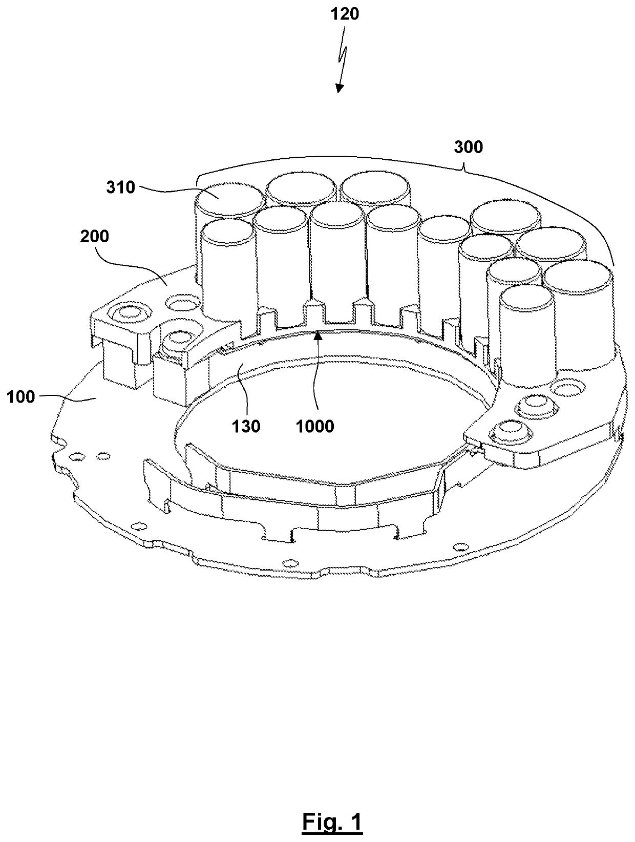
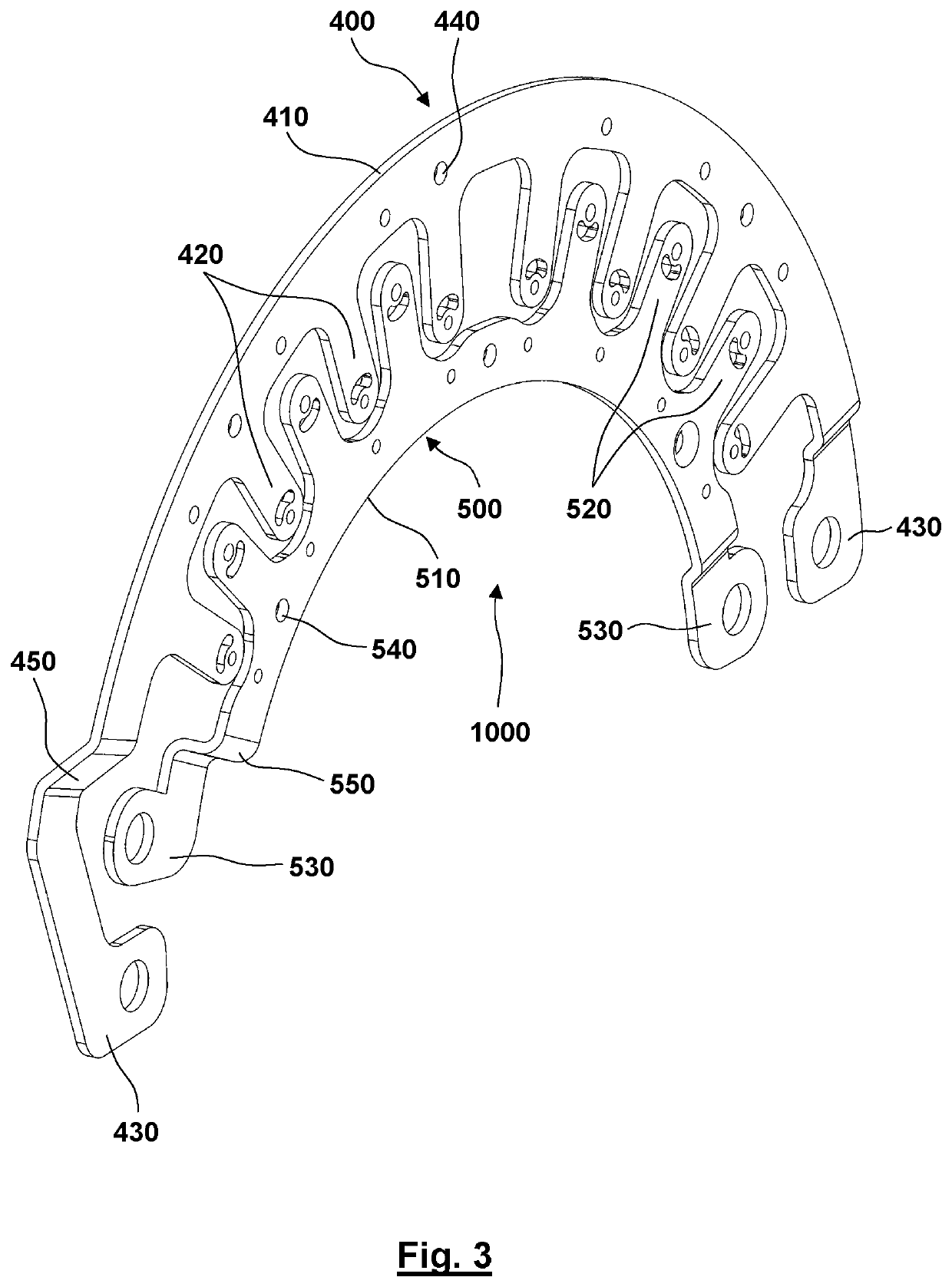
[0070]Referring to FIG. 1, a motor control module 120 for a vehicle brake system according to the present disclosure comprises: a circuit board 100 a capacitor assembly 300 and an electrically conductive connecting element 1000. The capacitor assembly 300 includes a plurality of capacitors 310. The plurality of capacitors 310 is connected to the electrically conductive connecting element 1000 to form (through the electrically conductive connecting element 1000) the capacitor assembly 300 in which the plurality of capacitors 310 are electrically connected to each other. The electrically conductive connecting element 1000 is electrically connected to the circuit board 100 and is disposed in a suspended state relative to the circuit board 100, such that a gap 130 is maintained between the capacitor assembly 300 and the circuit board 100.

[0071]After the capacitor assembly 300 is connected to the circuit board 100 through the electrically conductive connecting element 1000, a structure w...

embodiment ii

[0097]Embodiment II is different from Embodiment I in that in Embodiment II, the capacitor holder comprises a first holder and a second holder that are separately formed, wherein two ends of bodies of the capacitors are positioned on the first holder and the second holder, respectively. Structural designs of the first holder and the second holder may refer to the capacitor holder described in Embodiment I. The capacitors are positioned according to the solution described in Embodiment I. Because the upper and lower ends of the capacitors are both fixed by the holders, capacitor jitter may be better prevented. Preferably the first holder and the second holder are securely connected with each other, e.g., by screw connection, so as to hold and secure the capacitor assembly therebetween, which may prevent detachment of the first holder from the second holder, such that the capacitor holder's positioning of the capacitors is more stable.

[0098]It may be contemplated based on Embodiment I...

embodiment iii

[0100]Embodiment III is different from Embodiment I in that in Embodiment III the motor control module 120 further comprises an extended connecting element 1100 via which the electrically conductive connecting element 1000 and the circuit board 100 are electrically connected. The extended connecting element 1100 not only acts as an extended portion of the electrically conductive connecting element 1000, such that the electrically conductive connecting element 1000 may be electrically connected to a connection point that is relatively distant from the capacitor assembly 300 on the circuit board 100, but also may supply the electric energy of the capacitor assembly 300 to other electronic elements or circuits on the circuit board 100, respectively, to satisfy the power supply needs of the other elements and circuits on the circuit board 100. For example, the capacitor assembly 300 and the electrically conductive connecting element 1000 are disposed at a certain specific area of the ci...


PUM


Abstract

The present disclosure discloses a motor control module (120), an actuator, and an electromechanical brake apparatus, which relates to the technical field of mechanical braking. The present disclosure solves issues such as insufficient space and large size caused by directly connecting a circuit board and capacitors in the existing motor control modules. The motor control module (120) according to the present disclosure comprises a circuit board (100) and a capacitor assembly (300) including a plurality of capacitors (310) and an electrically conductive connecting element (1000) for electrically connecting the plurality of capacitors (310), the electrically conductive connecting element (1000) being electrically connected to the circuit board (100) and being disposed in a suspended state relative to the circuit board (100), such that a gap (130) is maintained between the capacitor assembly (300) and the circuit board (100). A region that is originally occupied by the capacitor assembly (300) on the circuit board (100) may be saved for mounting other electronic elements, such that mounting of the other electronic elements will not be restricted by the capacitor assembly (300). In this way, a smaller-sized circuit board may be used for a same number of electronic elements.

Description

CROSS REFERENCE TO RELATED APPLICATIONS[0001]This application is a continuation of International Application PCT / EP2019 / 058090 with an international filing date of Mar. 29, 2019 and claiming priority to co-pending Chinese Patent Application No. CN 201810298895.X entitled “Motor control module, actuator and electro-mechanical braking device”, filed on Mar. 30, 2018.FIELD OF THE INVENTION[0002]The present disclosure relates to the field of mechanical brake technologies, and more particularly to a motor control module for a vehicle brake system, an actuator having the motor control module, and an electromechanical brake apparatus applying the actuator. The vehicle brake system is in particular used in a utility vehicle or commercial vehicle or bus.BACKGROUND OF THE INVENTION[0003]An electromechanical brake (EMB) apparatus generally has an actuator and a disk brake. A torque generated by the actuator acts on a brake caliper of the disc brake via a mechanical structure, which realizes a ...

Claims


Application Information

Patent Timeline
Patent Type & Authority Applications(United States)
IPC IPC(8): F16D65/18F16D65/22
CPCF16D65/18F16D2121/24F16D65/22H02P29/00H01G4/002H01G4/38B60T13/74B60T13/741H02K11/33H02K3/522H02K3/50H02K2203/03H02K2211/03F16D2131/02F16D2250/0076H01G4/224
Inventor WU, GANGLINDQVIST, ANDERSNILSSON, ANDERSSONG, ZENGLAIDONG, XIANBINFEI, YIBO
Owner HALDEX BRAKE PROD AB
Learn More