
Nonadjustable focusing type camera module

a camera module and non-adjusting technology, applied in the field of camera modules, can solve the problems of long time, increased manufacturing and material costs, and reduced competitiveness of the camera module as a product, and achieve the effects of reducing the manufacturing cost of the mold and material cost, reducing design time, and simplifying the mold

Inactive Publication Date: 2009-06-30
SAMSUNG ELECTRO MECHANICS CO LTD
View PDF21 Cites 17 Cited by
  • Summary
  • Abstract
  • Description
  • Claims
  • Application Information

AI Technical Summary

Benefits of technology

This design simplifies manufacturing, reduces costs, enhances reliability by preventing foreign matter-induced image deterioration, and allows for more efficient production with improved optical performance.

Problems solved by technology

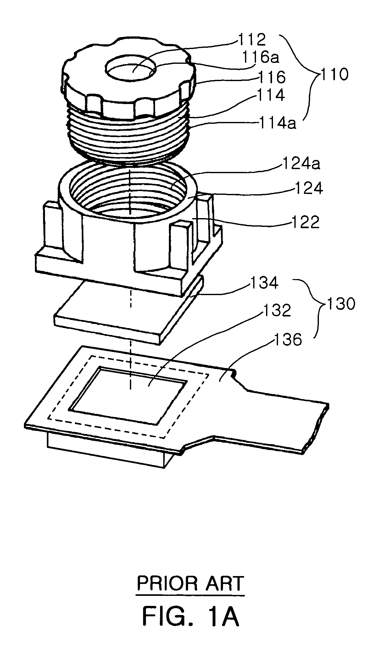
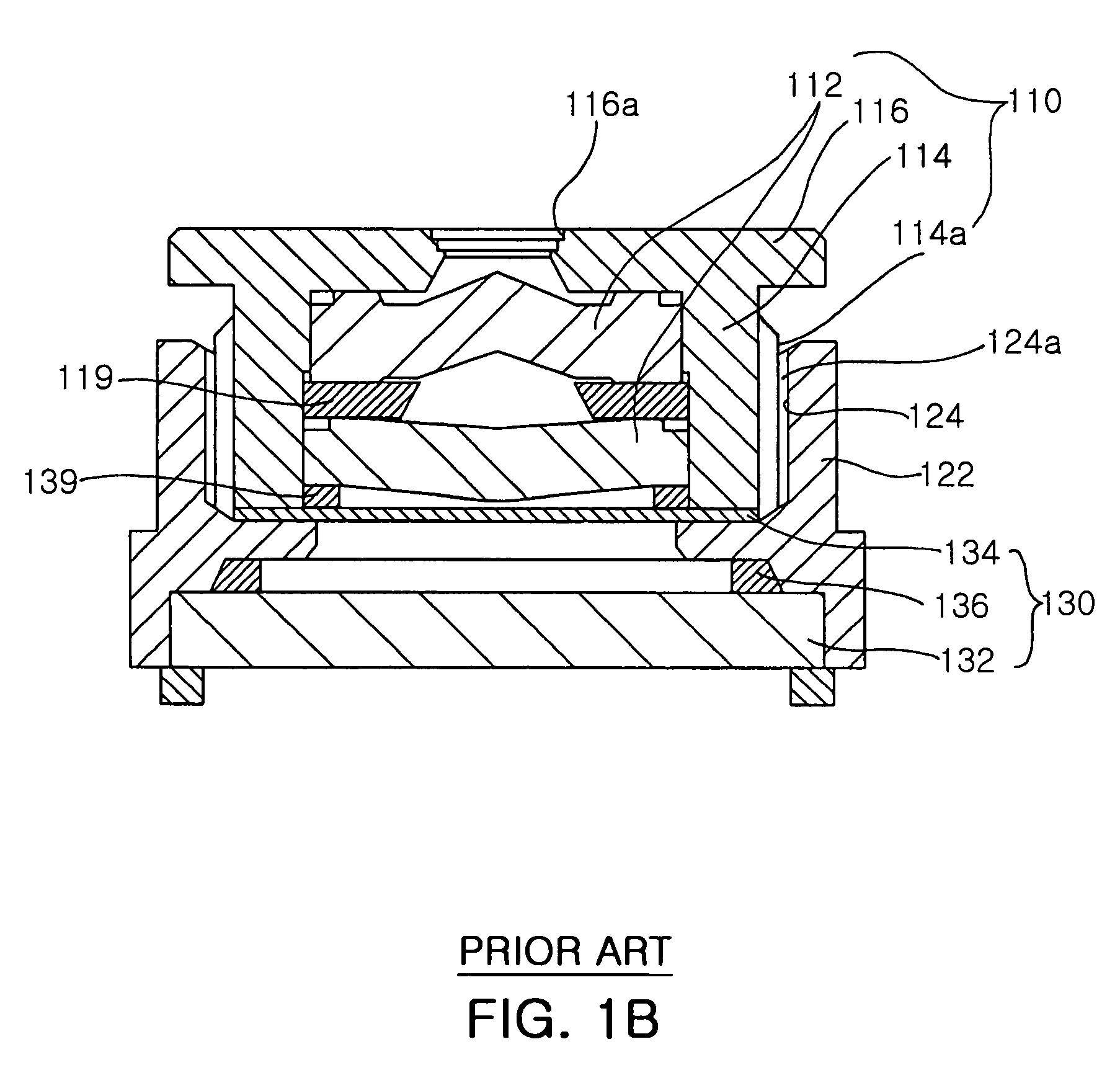
However, since the barrels 114 and 114′ and the housing 122 employed in the conventional camera module should be manufactured by separate molds due to the fact that the structure of the barrels 114 and 114′ to accommodate the lenses 112 and 112′ must be screwed to the housing 122, it takes a long time to design a new product and manufacturing costs and material costs are increased so that the camera module as a product loses competitiveness in view of costs and a limit to reduce its size.
Moreover, it takes a long time to assemble the barrels 114 and 114′ with the housing 122 because of the small size of the lenses and the spacer assembled in the barrels 114 and 114′ so that workability for the assembly is deteriorated.
Due to these focusing differences the resolution is deteriorated so that the reliability of the product decreases.
Particularly, when there is error in the focusing process, the resolution of the camera module deteriorates, and since it takes a long time to assemble and complete the camera module due to a complicated assembling process, the productivity is decreased.
Thus, the reliability of the product is deteriorated.

Method used


Image

  • Nonadjustable focusing type camera module
  • Nonadjustable focusing type camera module
  • Nonadjustable focusing type camera module

Examples


Embodiment Construction

[0055]Hereinafter, the present invention will be described in detail with reference to the accompanying drawings as follows.

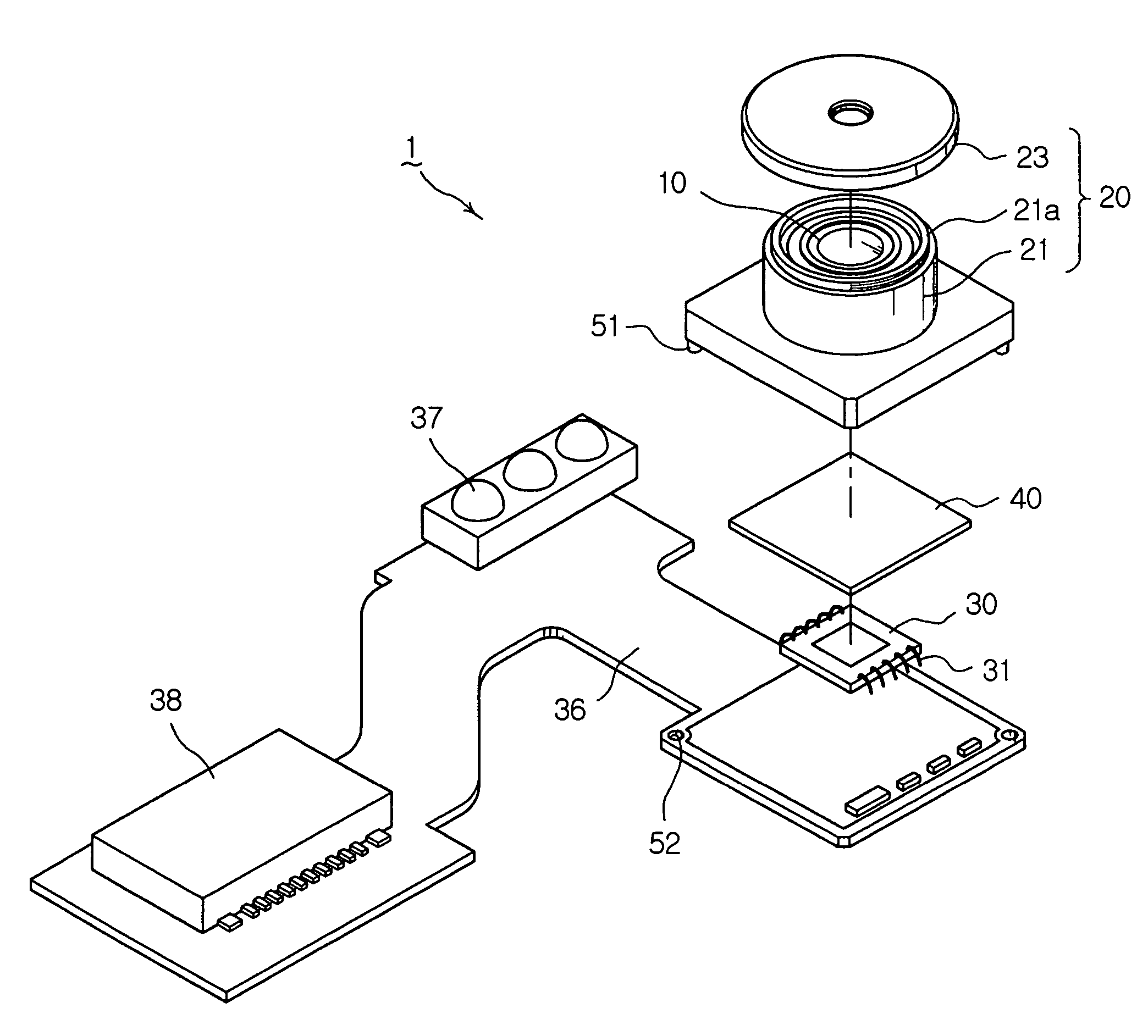
[0056]FIG. 3 is a view illustrating a nonadjustable focusing type camera module according to a first preferred embodiment of the present invention, in which FIG. 3a is an exploded perspective view of the nonadjustable focusing type camera module according to the first preferred embodiment of the present invention, and FIG. 3b is a sectional view illustrating an assembly of the nonadjustable focusing type camera module according to the first preferred embodiment of the present invention. The camera module 1 according to the first preferred embodiment of the present invention includes a lens assembly 10, a lens accommodating part 20, an image sensor 30, and a filter member 40.

[0057]In other words, the lens assembly 12 includes at least one lens 12 arranged along the optical axis O and is accommodated in the lens accommodating part 20 having a predetermined inner ...


PUM


Abstract

A nonadjustable focusing type camera module includes a lens assembly having at least one lens, a lens accommodating part mounted on an upper surface of a substrate, and a barrel having an inner space in which the lens assembly is arranged along an optical axis. An upper cap having an incident hole formed in a front center thereof is fixed to the upper side of the barrel to apply pressure to the lens assembly along the optical axis. The camera module further includes an image sensor having an image forming plane on which a light passed through the lens is focused. The sensor is electrically connected to the substrate to transmit the focused image, and a filter is disposed between the lens assembly and the image sensor.

Description

RELATED APPLICATION[0001]The present invention is based on, and claims priority from, Korean Application Number 2005-28821, filed Apr. 7, 2005, the disclosure of which is incorporated by reference herein in its entirety.BACKGROUND OF THE INVENTION[0002]1. Field of the Invention[0003]The present invention relates to a camera module, and more particularly, to a camera module in which a component for accommodating a lens and components installed on a substrate are integrally formed into one body to simplify a mold, to reduce design time, to reduce manufacturing costs of the mold and material costs, and to minimize volume of the camera module.[0004]2. Description of the Related Art[0005]Generally, a camera module includes a lens part containing a lens, a housing coupled with the lens part, and a sensor part including an IR filter, an image sensor, and the like.[0006]FIG. 1a is an exploded perspective view of the conventional camera module, and FIG. 1b is a vertical sectional view of the...

Claims


Application Information

Patent Timeline
Patent Type & Authority Patents(United States)
IPC IPC(8): G03B7/099F21V9/04H04N5/225G03B17/00G02B7/02G03B11/00H01L27/14H04N25/00
CPCG03B7/09908G03B11/00H01L27/14618H01L27/14625H04N5/2253H04N5/2254H04N5/2257H01L2224/48091H04N23/54H04N23/57H04N23/55H01L2924/00014G03B17/12G02B7/04G02B7/022
Inventor GO, MIN CHUL
Owner SAMSUNG ELECTRO MECHANICS CO LTD
Learn More