Method for locating points or lines of interest on a railway track

a railway track and point of interest technology, applied in railway auxiliaries, transportation and packaging, instruments, etc., can solve the problems of cumulative odometric errors, system management of curved tracks, and inability to take into account potential perpendicularity defects between linear cameras and tracks

Active Publication Date: 2021-01-28
MATISA MATERIEL IND SA
View PDF0 Cites 2 Cited by
  • Summary
  • Abstract
  • Description
  • Claims
  • Application Information

AI Technical Summary

Benefits of technology

[0011]The linear camera offers the advantage of being highly insensitive to parasitic movements, notably vibrations undergone by the locating system progressing on the railway track, which may be further accentuated if the locating system is fixed or hitched to an intervention machine on the railway track. Furthermore, the time of formation of a pixel of the linear image is shorter with respect to matrix technologies. The latency and the uncertainty of positioning which could be introduced by an extended exposure and a too long formation time are thus reduced.
[0094]It is possible, if appropriate, to mix a camera and a feeler, on the same rail or on two different rails. It is thus possible to carry out an interpolation between the orientation data delivered by the two orientation matrix cameras to estimate the orientation of the transposition chassis. The presence of at least one sensor (feeler or matrix camera) above each rail of the railway track also makes it possible to offset the absence of a rail on a section of the track, notably when the transposition system progresses along a track apparatus, for example points. It is also possible to choose a specific rail orientation in curves, for example the rail situated inside the curve.

Problems solved by technology

Furthermore, odometric errors linked for example to sliding or to the angular inscription of the feeler wheel with respect to the neutral line of the rail are cumulative.
Finally, this system does not manage curved tracks.
Furthermore, potential perpendicularity defects between the linear camera and the track are not taken into account.

Method used


Image

  • Method for locating points or lines of interest on a railway track
  • Method for locating points or lines of interest on a railway track

Examples


Embodiment Construction

[0004]The invention notably aims to overcome the drawbacks of the prior art and to propose means enabling a precise early locating of points or lines of interest on a railway track, delimiting if appropriate the zones of interest for the later intervention of a tool borne and driven by an intervention machine running on the track.

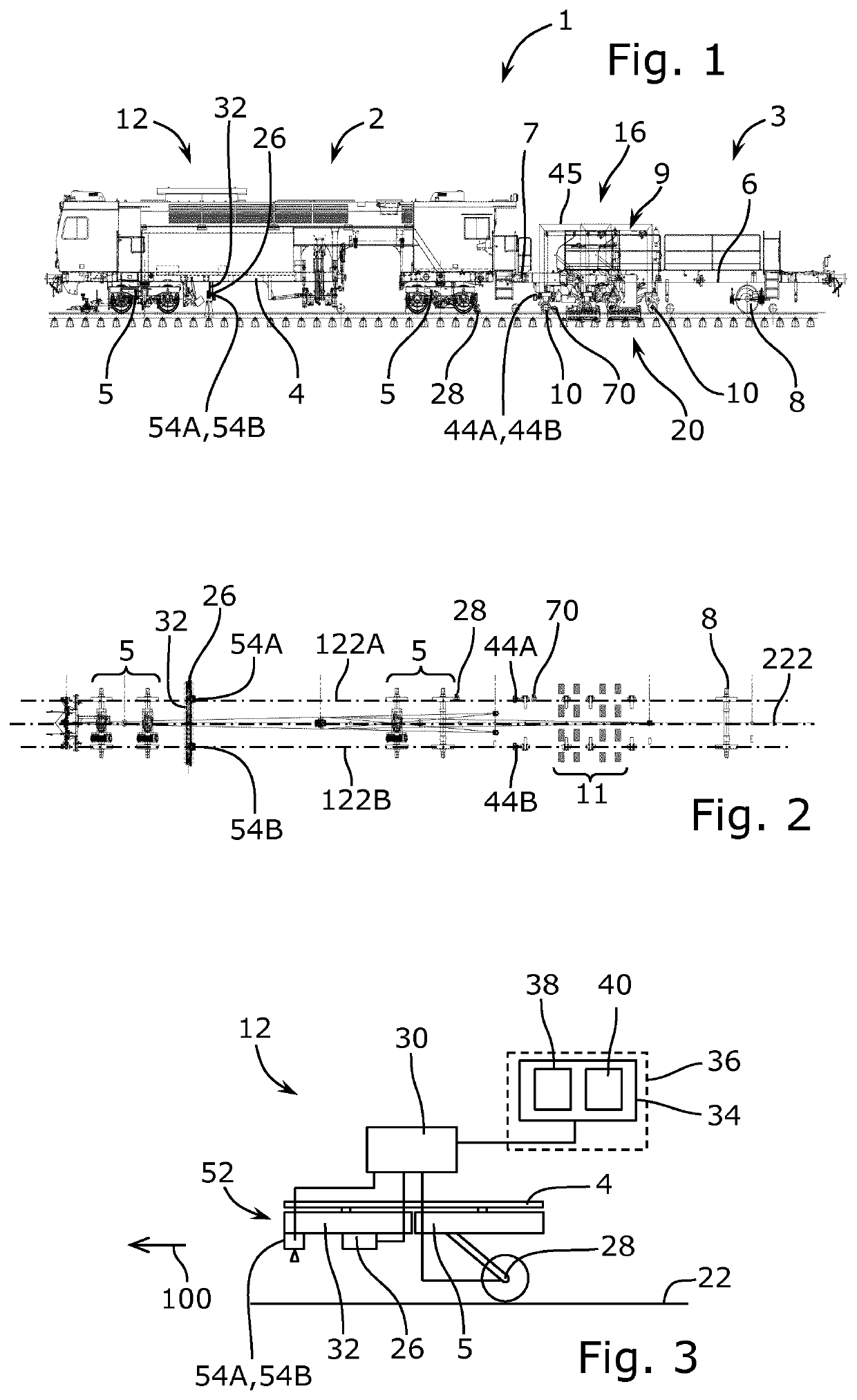
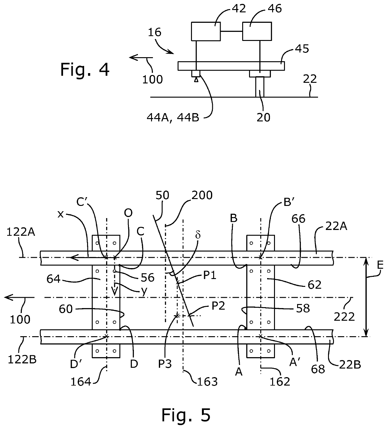
[0005]For this purpose, according to a first aspect of the invention, a method for locating a railway track is proposed, carried out by a railway locating system comprising at least one linear camera pointing at the railway track and one or more odometers, the railway locating system progressing on the railway track in a direction of progression, the locating method comprising the following actions:[0006]repeatedly acquiring, with the odometer(s), progression data of the railway locating system on the railway track in the direction of progression,[0007]repeatedly acquiring, with the linear camera pointing at the railway track, instantaneous linear optical d...


PUM


Abstract

In order to locate points or lines of interest (A, B, C, D, A′, B′, C′, D′, 162, 163, 164) of a railway track (22), by means of a railway locating system (12), progressing on the railway track (22), a linear camera (26) pointing at the railway track (22) repeatedly acquires instantaneous linear optical data along an instantaneous measurement line (50), and an orientation device (52) of the railway locating system (12) repeatedly acquires orientation data of the railway locating system (12) with respect to a reference line (22A) of the railway track (22). By processing at least the instantaneous linear optical data, a potentially distorted bitmap image is constructed of a zone of the surface of the railway track (22), then points or lines of interest (A, B, C, D, A′, B′, C′, D′, 162, 163, 164) are identified in the potentially distorted bitmap image, before determining rectified coordinates of the points or lines of interest (A, B, C, D, A′, B′, C′, D′, 162, 163, 164), as a function of potentially distorted coordinates of the points or lines of interest (A, B, C, D, A′, B′, C′, D′, 162, 163, 164) in a reference system of the potentially distorted bitmap image and orientation data.

Description

TECHNICAL FIELD OF THE INVENTION[0001]The invention relates to the use of a railway vehicle for auscultation of a railway track or for work on a railway track, notably for its construction, its upkeep, its maintenance, its repair, its renewal or its dismantling. It also relates to the early locating of points of interest on a railway track, delimiting if appropriate zones of interest for the later intervention of an intervention tool on the track, borne and maneuvered by a machine running on the track. It also relates to the transposition of such a locating for the later use thereof, notably for a later auscultation of the track by means of an auscultation apparatus or for later intervention on the track by means of an intervention tool.PRIOR ART[0002]The document U.S. Pat. No. 4,986,189 describes an intervention machine for the maintenance or the repair of a railway track, which comprises intervention tools intended to work while the machine advances while running on the railway tr...

Claims


Application Information

Patent Timeline
Patent Type & Authority Applications(United States)
IPC IPC(8): B61L23/04B61K9/08G06T7/00G01B11/24B61L25/02
CPCB61L23/042B61K9/08G06T7/0004B61L15/009B61L25/025B61L23/041G01B11/24B61L23/04B61L15/0072B61L2205/04G06T7/001
Inventor STUPAR, MILANCHINOUNE, YOUCEF
Owner MATISA MATERIEL IND SA
Why Eureka
Try Eureka