
Method for irradiating a powder layer in additive production using continuously defined production parameters

Pending Publication Date: 2020-11-12
SIEMENS ENERGY GLOBAL GMBH & CO KG
View PDF1 Cites 0 Cited by
  • Summary
  • Abstract
  • Description
  • Claims
  • Application Information

AI Technical Summary

Benefits of technology

The present invention aims to provide means to improve the quality of additively produced components by solving structural quality issues. The described method allows for faster exposure of the contour without interruptions and reduces the risk of crack and defect formation during additive production. The surface quality of components, including inner-lying surfaces, is also improved. The described means enable the production of components with lower densities of defects, crack centers, and likelihood of defect or hot crack formation, resulting in improved structure and dimensional compliance. In one configuration, the production parameter is a geometry of a contour irradiation pattern for the additive production of the component, which ensures stable and continuous guidance of the melt bath over the powder bed and prevents abrupt interruptions.

Problems solved by technology

Despite a certain “design freedom”, for example of selective melting methods, the additive production of overhanging structures of the described components is known to represent a great challenge.
This leads to an unfavorably interrupted, intermittent or discontinuous contour irradiation and therefore inefficiently long process or construction times, and additionally to instabilities in the melt bath during the powder solidification, since for example repeated “ignition”, “approaching” and / or alignment of the irradiation apparatus required for the solidification is necessary upon each interruption or change in the irradiation path.

Method used


Image

  • Method for irradiating a powder layer in additive production using continuously defined production parameters
  • Method for irradiating a powder layer in additive production using continuously defined production parameters
  • Method for irradiating a powder layer in additive production using continuously defined production parameters

Examples


Embodiment Construction

[0050]In the exemplary embodiments and figures, elements which are the same or have the same effect may respectively be provided with the same references. The elements represented and their size proportions with respect to one another are not in principle to be regarded as true to scale; rather, individual elements may be represented exaggeratedly thick or largely dimensioned for better representability and / or for better comprehensibility.

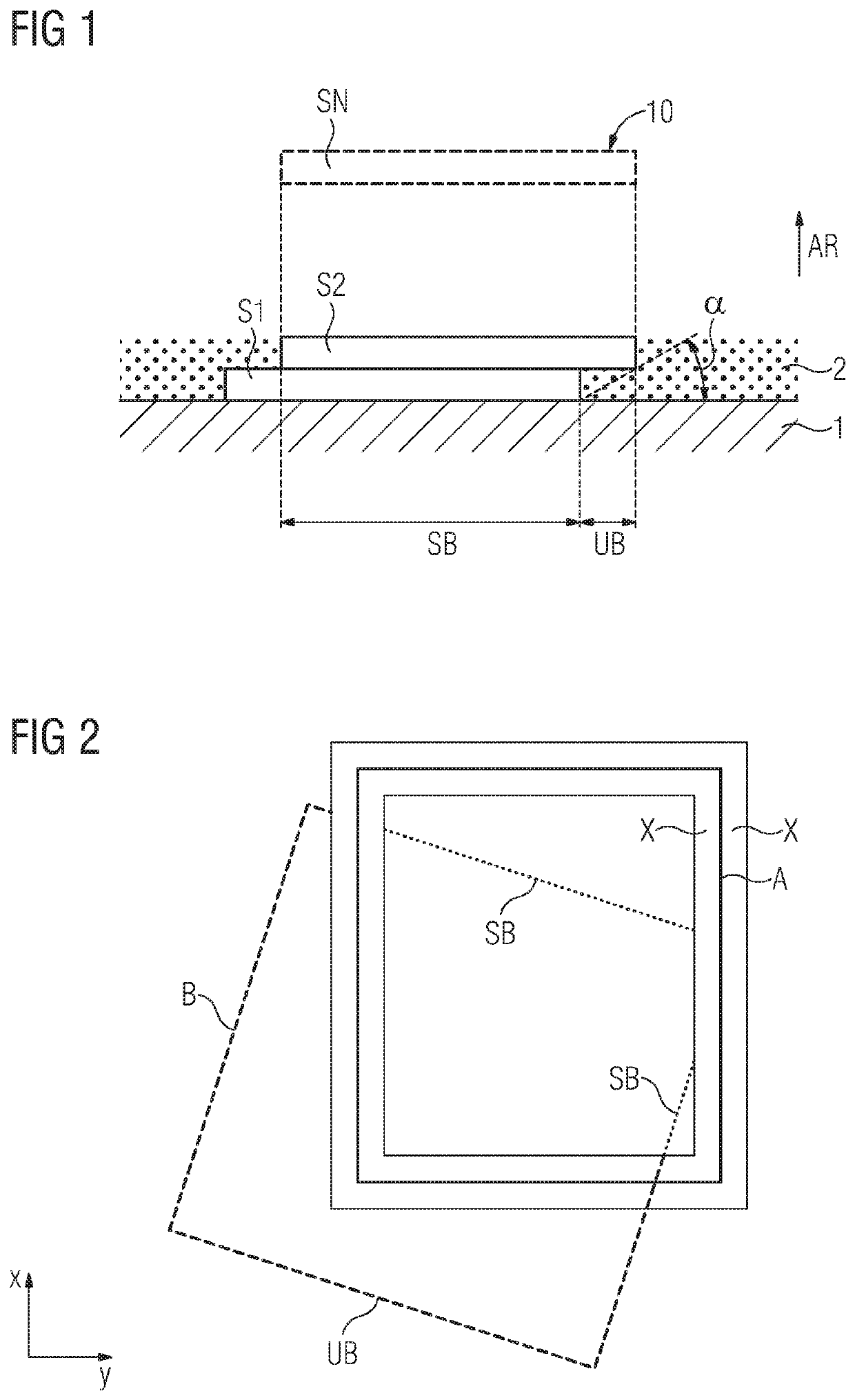
[0051]FIG. 1 shows a schematic sectional or side view of at least one part of a component 10 to be additively produced. The component 10 is advantageously indicated during its additive, generative or layerwise production, a first layer S1 and a second layer S2, arranged above the first layer along a construction direction AR, already having been selectively irradiated from an irradiation device (not explicitly shown) and accordingly solidified and produced.

[0052]The solidification, for example by a laser or electron beam (cf. SLM and EBM methods) i...


PUM

PropertyMeasurementUnit
Sizeaaaaaaaaaa
Densityaaaaaaaaaa
Energy densityaaaaaaaaaa

Abstract

A method for providing data for selectively irradiating a powder layer in additive production, the method includes: providing a predefined component geometry for a component; dividing the component geometry into at least one first component layer and an overlying second component layer for additive production, wherein a contour of the second component layer is incongruent with a contour of the first component layer; and continuously defining at least one production parameter for additively producing the second component layer in region of a molten bath of a contour of the first component layer. A corresponding component is produced and a computer program product implements the method.

Description

CROSS REFERENCE TO RELATED APPLICATIONS[0001]This application is the US National Stage of International Application No. PCT / EP2018 / 075154 filed 18 Sep. 2018, and claims the benefit thereof. The International Application claims the benefit of European Application No. EP17194340 filed 2 Oct. 2017. All of the applications are incorporated by reference herein in their entirety.FIELD OF INVENTION[0002]The present invention relates to a method for, or as part of, an additive production method. The invention relates, in particular, to the provision of data or information for the selective irradiation of a powder layer in additive production.[0003]The present invention also relates to a corresponding additive production method and to a component produced according to this method. Furthermore, the present invention relates to a computer program, or computer program product, and to a corresponding computer-readable medium.BACKGROUND OF INVENTION[0004]Generative or additive methods for the pro...

Claims


Application Information

Patent Timeline
IPC IPC(8): B29C64/153B29C64/268B29C64/393B29C64/364
CPCB29C64/268B29C64/393B33Y10/00B29C64/153B29C64/364B33Y50/02G05B19/4099B33Y50/00B29C64/386Y02P10/25B22F10/28B22F10/385
Inventor GEISEN, OLE
Owner SIEMENS ENERGY GLOBAL GMBH & CO KG
Learn More