
MRI system and method for detection and correction of patient motion

a patient motion and magnetic resonance imaging technology, applied in the field of magnetic resonance imaging, can solve the problems of blurriness, artifacts, and other inconsistencies in patient motion, and add to cost and patient setup time, so as to improve the effect of motion

Active Publication Date: 2020-10-29
GENERAL ELECTRIC CO
View PDF4 Cites 5 Cited by
  • Summary
  • Abstract
  • Description
  • Claims
  • Application Information

AI Technical Summary

Benefits of technology

This approach automatically detects and corrects for patient motion, improving MRI scan throughput, reducing the need for re-scans, and enhancing image quality by allowing real-time adaptation and reconstruction of motion-free images.

Problems solved by technology

Patient motion is one of the biggest sources of inefficiency in clinical MRI, often requiring re-scans or even second visits by the patient.
In particular, patient motion can cause blurriness, artifacts, and other inconsistencies in MR images.
Certain approaches to correct motion require either some sort of hardware for monitoring the motion (adding to cost and patient setup time), or navigator sequences (which take time away from the imaging sequence).

Method used


Image

  • MRI system and method for detection and correction of patient motion
  • MRI system and method for detection and correction of patient motion
  • MRI system and method for detection and correction of patient motion

Examples


Embodiment Construction

e scan, and aggregating a final motion state when motion is detected;

[0029]FIG. 23 is an embodiment of an algorithm for performing a scan, monitoring for motion during the scan, and adapting to the motion during the scan when motion is detected;

[0030]FIG. 24 is an embodiment of a method of reconstructing a motion-free image from motion-corrupted datasets; and

[0031]FIG. 25 is another embodiment of a method of reconstructing a motion-free image from motion-corrupted datasets.

DETAILED DESCRIPTION

[0032]One or more specific embodiments will be described below. In an effort to provide a concise description of these embodiments, all features of an actual implementation may not be described in the specification. It should be appreciated that in the development of any such actual implementation, as in any engineering or design project, numerous implementation-specific decisions must be made to achieve the developers' specific goals, such as compliance with system-related and business-related...


PUM


Abstract

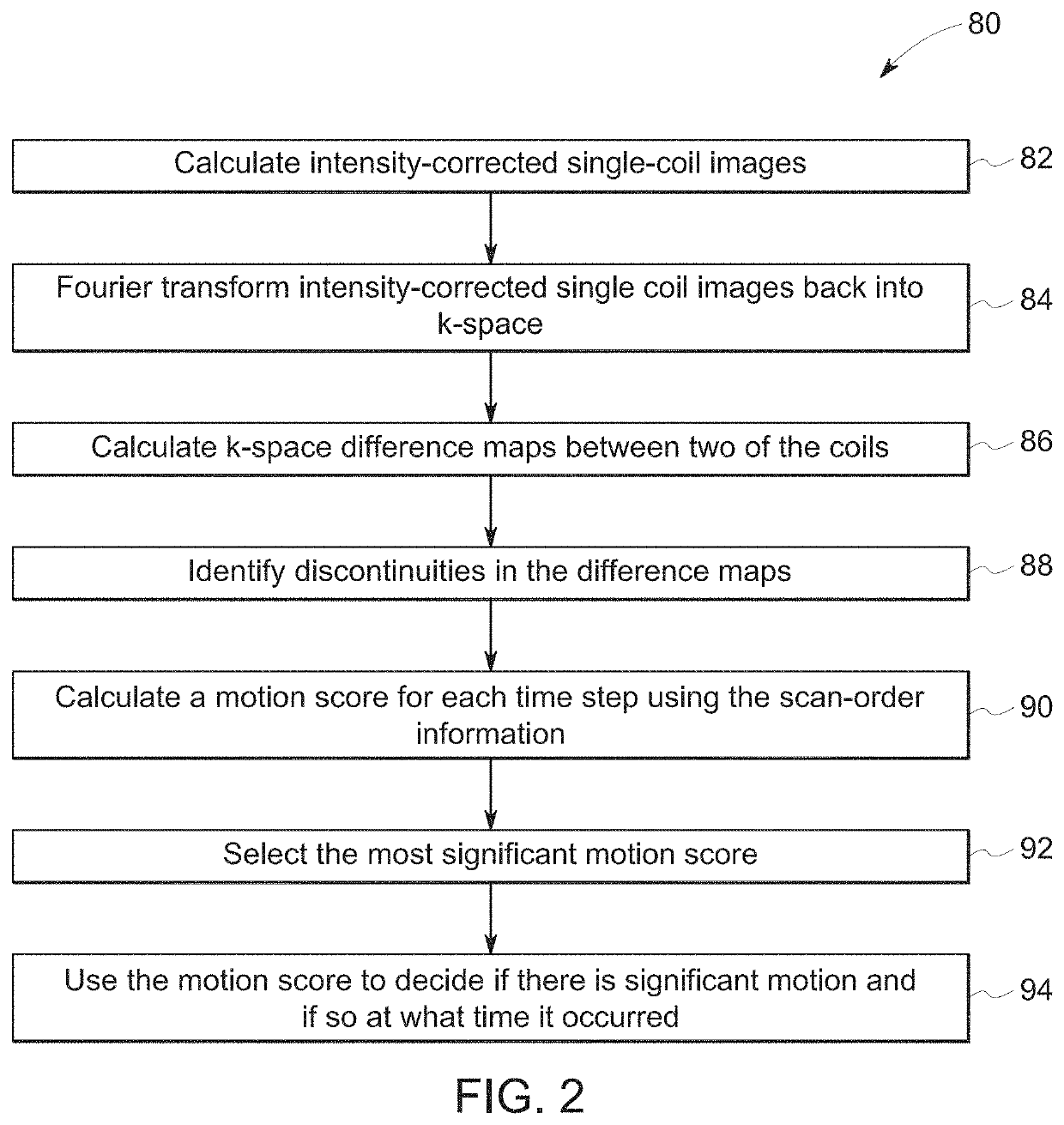
A system and method for detecting, timing, and adapting to patient motion during an MR scan includes using the inconsistencies between calculated images from different coil-array elements to detect the presence of patient motion and, together with the k-space scan-order information, determine the timing of the motion during the scan. Once the timing is known, various actions may be taken, including restarting the scan, reacquiring those portions of k-space acquired before the movement, or correcting for the motion using the existing data and reconstructing a motion-corrected image from the data.

Description

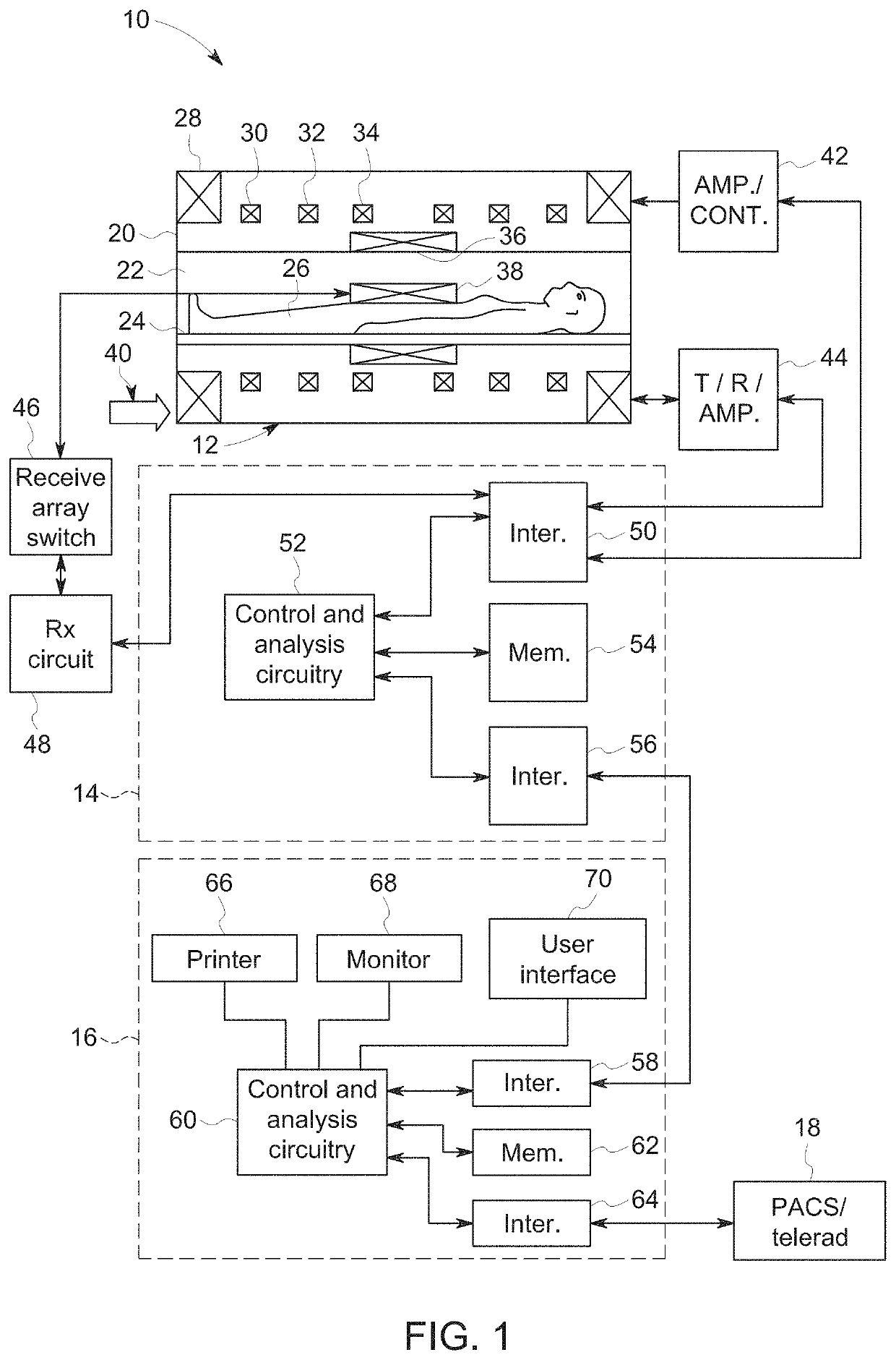
BACKGROUND[0001]In general, magnetic resonance imaging (MRI) examinations are based on the interactions among a primary magnetic field, a radiofrequency (RF) magnetic field and time varying magnetic gradient fields with gyromagnetic material having nuclear spins within a subject of interest, such as a patient. Certain gyromagnetic materials, such as hydrogen nuclei in water molecules, have characteristic behaviors in response to external magnetic fields. The precession of spins of these nuclei can be influenced by manipulation of the fields to produce RF signals that can be detected, processed, and used to reconstruct a useful image.[0002]Patient motion is one of the biggest sources of inefficiency in clinical MRI, often requiring re-scans or even second visits by the patient. In particular, patient motion can cause blurriness, artifacts, and other inconsistencies in MR images. Certain approaches to correct motion require either some sort of hardware for monitoring the motion (addin...

Claims


Application Information

Patent Timeline
Patent Type & Authority Applications(United States)
IPC IPC(8): A61B5/055G01R33/565G01R33/48G01R33/56
CPCG01R33/4818A61B5/0555G01R33/56509G16H30/40G01R33/5608A61B5/055A61B5/7207A61B2576/00A61B5/7257G16H30/20G01R33/5611G01R33/482G06T5/10G06T7/262G06T2207/10088G06T2207/20201G06T2207/30016G06T5/50G06T2207/20084G06T5/70G06T5/60
Inventor BRADA, RAFAEL SHMUELHARDY, CHRISTOPHER JUDSONAHN, SANGTAEHEUKENSFELDT JANSEN, ISABELLEMALKIEL, ITZIKROTMAN, MICHAELWEIN, RON
Owner GENERAL ELECTRIC CO
Learn More