
Smartphone vapor chamber of stainless steel material coated with sio2

Inactive Publication Date: 2020-10-22
POLAR&CO
View PDF0 Cites 0 Cited by
  • Summary
  • Abstract
  • Description
  • Claims
  • Application Information

AI Technical Summary

Benefits of technology

The present invention relates to a stainless steel vapor chamber coated with a SiO2 material that reduces thermal resistance to improve heat transfer. The SiO2 coating is applied to the interior of the vapor chamber to improve the heat transfer effect and reduce the temperature difference between the hot and cooling sides, similar to pure copper. The coated surface has increased strength when coupled to a smartphone frame. The stainless steel vapor chamber has a reduced thermal resistance, making it more efficient in heat transfer.

Problems solved by technology

Moreover, due to a slim structure of the smartphones, it is not easy to install an effective cooling unit in the smartphones.
Therefore, high heat is generated in the smartphones, and excessive heat generated in the smartphones causes discomfort and anxiety to a user.
That is, since it has been reported that the smartphones have been exploded due to battery failure, or the like, when the smartphones become too hot, a user may be in great anxiety.
Aside from the explosion, heat generated in the smartphones may damage semiconductors inside the smartphones or cause operation errors, and thus, it is necessary to radiate heat and cool the heat as quickly as possible.
Therefore, a stainless steel material with low thermal conductivity (12 to 45 w / mk) is not used and a vapor chamber employing the stainless steel material is not available in the market at present.
However, as the vapor chamber made of a copper material is employed, there are problems in that an inner thickness of the vapor chamber becomes as much as 0.5 mm thicker, the vapor chamber is easily damaged by a slight impact or contact due to softness of the copper material, and both surfaces of the vapor chamber are adhered to an inner frame of a smartphone such that thermal resistance is generated to degrade radiation of heat.

Method used


Image

  • Smartphone vapor chamber of stainless steel material coated with sio2
  • Smartphone vapor chamber of stainless steel material coated with sio2
  • Smartphone vapor chamber of stainless steel material coated with sio2

Examples


first embodiment

[0048]1. The first embodiment proposes a general adhesion form in which the smartphone vapor chamber 20 of the present invention is correspondingly adhered and fixed to one surface of the smartphone frame 10.

[0049]2. The second embodiment is configured such that, when the smartphone vapor chamber 20 is integrally manufactured with the smartphone frame 10, a thickness of the smartphone frame 10 is not affected. The second embodiment includes the smartphone frame 10 in which a mounting part 12 is formed to vertically penetrate a base 11 and a first bump 13 is formed on an edge of one surface of the mounting part 12, and the smartphone integrated vapor chamber 20 in which the upper and lower plates 21 and 22 are adhered to form the accommodation space 24 for a working fluid in the smartphone integrated vapor chamber 20, and a second bump 23 is correspondingly mounted on the mounting part 12 of the smartphone frame 10 and is formed to correspond to the first bump 13 on an edge of one su...

second embodiment

[0050]More specifically, the second embodiment is a case in which a separate smartphone integrated vapor chamber 20 is mounted on the smartphone frame 10.

[0051]The smartphone frame 10 is configured such that the mounting part 12 is formed to vertically penetrate the base 11 of the smartphone frame 10 at a position which is predetermined by a user, and the first bump 13 is formed to be recessed on the edge of one surface of the mounting part 12 (which is a surface on which the smartphone integrated vapor chamber 20, which will be described below, will be correspondingly mounted).

[0052]The smartphone integrated vapor chamber 20 is configured such that the upper and lower plates 21 and 22 (where the upper plate 21 is a vapor plate (made of a stainless steel (SUS) material) and the lower plate 22 is a wick plate (made of a SUS material)) are vertically integrally adhered. The smartphone integrated vapor chamber 20 is correspondingly adhered to the mounting part 12 of the above-described...

third embodiment

[0055]Alternatively, both of holes and protrusions may be alternately formed on the first bump 13 and the second bump 23 (this is also applicable to the third embodiment which will be described below).

[0056]Further, a brazing adhesive is inserted around an edge of the accommodation space 24 and then the smartphone integrated vapor chamber 20 is assembled with the accommodation space 24 by performing a brazing process in a vacuum brazing furnace at a preset temperature. After the brazing process, the accommodation space 24 is filled with the working fluid and vacuumed and then an inlet 26 for the working fluid is directly manufactured by welding without a separate injection line for injecting a working fluid.

[0057]3. As in the second embodiment, the third embodiment is configured such that, when a smartphone integrated vapor chamber 20 is integrally manufactured with a smartphone frame 10, the thickness of the smartphone frame 10 is not affected. The third embodiment includes the sma...


PUM


Abstract

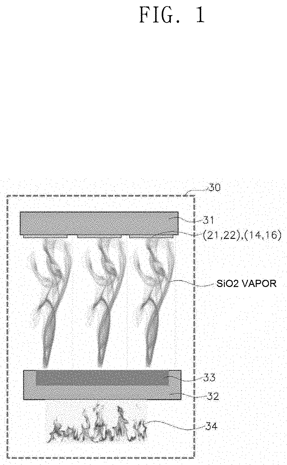
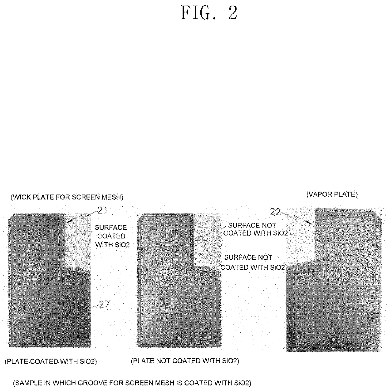
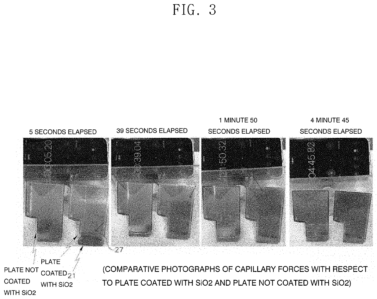
Provided is a smartphone vapor chamber of a stainless steel material coated with SiO2. The smartphone vapor chamber is configured such that strength of the existing smartphone vapor chamber, which employs a copper material, is increased by employing a stainless steel material, movement of a working fluid is facilitated by forming a wick groove in the smartphone vapor chamber, all surfaces or any one surface of upper and lower plates forming the smartphone vapor chamber is coated with SiO2. Owing to the SiO2 coating, a circulation of the working fluid is accelerated by improving heat transfer, an infiltration rate, and a capillary force, heat radiation is maximized, and the smartphone vapor chamber has effects of having thermal resistance and operation performance which are similar to those of a vapor chamber using copper and of not affecting a variation in thickness of a frame.

Description

BACKGROUND1. Field of the Invention[0001]The present invention relates to a smartphone vapor chamber of a stainless steel material coated with SiO2, in which stainless steel is employed as a material of a vapor chamber which serves as a cooling device for cooling a semiconductor in a smartphone, and a surface of the stainless steel is coated with SiO2 having high thermal conductivity so as to improve a heat transfer effect of the stainless steel.2. Discussion of Related Art[0002]Describing basic structures of smartphones, current smartphones have a structure in which a frame structure made of stainless steel, magnesium, or aluminum is provided inside the smartphone, a display is mounted at a front side of the frame, and a driving circuit and a battery are mounted at a rear side of the frame.[0003]In the smartphones, since a processing speed of a central processing unit (CPU) is fast and the CPU performs various operations, an operation amount of the CPU is increased, and thus, heat ...

Claims


Application Information

Patent Timeline
IPC IPC(8): H05K7/20F28D15/04
CPCF28D15/046H01L23/427H05K7/20336H04M1/0202H05K7/20309
Inventor LEE, KIWOOKIM, JONGSUNKIM, SANGGYUNGCUI, JINGLONG
Owner POLAR&CO
Learn More