
Fire box of inverse push type destructor

A waste incinerator and furnace technology, applied in the direction of incinerator, combustion method, combustion type, etc., can solve the problems that affect the stability of the incinerator, reduce the processing capacity of the incinerator, and the garbage cannot be completely burned, and achieve the best heat radiation effect Excellent, improve the utilization rate of garbage, shorten the burning time

Active Publication Date: 2010-06-09
CHONGQING SANFENG COVANTA ENVIRONMENTAL IND
View PDF9 Cites 0 Cited by
  • Summary
  • Abstract
  • Description
  • Claims
  • Application Information

AI Technical Summary

Problems solved by technology

[0004] In the prior art, the garbage in the hearth of the Martin furnace is burned in an orderly manner through the drying area, burning area, and burnout area of ​​the grate. Due to the unique nature of Chinese garbage, there is more moisture, which will lead to drying or burning in the corresponding area. Incomplete, so that the garbage cannot be completely burned, and the ash contains unburned garbage, which affects the utilization rate of garbage
If the purpose of burnout is achieved, it is necessary to increase the residence time of the garbage in the furnace, resulting in a decrease in combustion efficiency, a reduction in the processing capacity of the incinerator, and affecting the stability of the incinerator.

Method used


Image

  • Fire box of inverse push type destructor
  • Fire box of inverse push type destructor

Examples


Embodiment 1

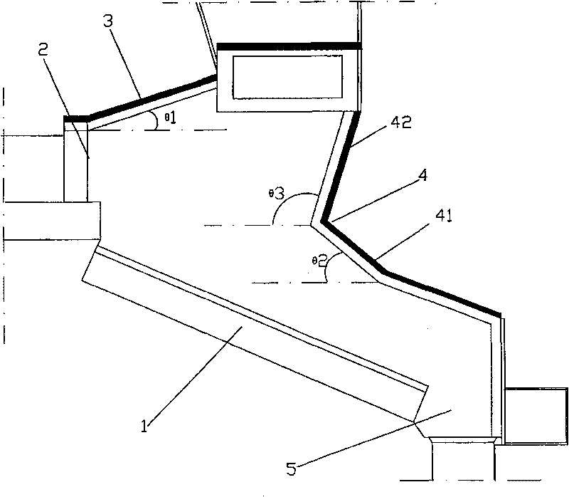
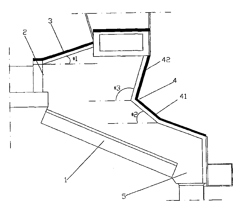
[0017] Accompanying drawing is the real structural representation of the present invention, as shown in the figure: the reverse thrust type refuse incinerator hearth of the present invention, comprises left and right side wall, front wall 3, rear wall 4 and fire grate 1 at the bottom, garbage inlet 2 It is arranged at the lower part of the front wall 3, and the ash outlet 5 is arranged at the lower part of the rear wall 4. The included angle θ1 between the front wall 3 and the horizontal plane is 13.5°. The included angle θ2 between 41 and the horizontal plane is 42°, and the included angle θ3 between the upper part 42 of the rear wall 4 and the horizontal plane is 104°.

Embodiment 2

[0019] Accompanying drawing is the real structural representation of the present invention, as shown in the figure: the reverse thrust type refuse incinerator hearth of the present invention, comprises left and right side wall, front wall 3, rear wall 4 and fire grate 1 at the bottom, garbage inlet 2 It is arranged at the lower part of the front wall 3, and the ash outlet 5 is arranged at the lower part of the rear wall 4. The included angle θ1 between the front wall 3 and the horizontal plane is 10°. The angle θ2 between the lower portion 41 and the horizontal plane is 38°, and the angle θ3 between the upper portion 42 of the rear wall 4 and the horizontal plane is 102°.

Embodiment 3

[0021] Accompanying drawing is the real structural representation of the present invention, as shown in the figure: the reverse thrust type refuse incinerator hearth of the present invention, comprises left and right side wall, front wall 3, rear wall 4 and fire grate 1 at the bottom, garbage inlet 2 It is arranged at the lower part of the front wall 3, and the ash outlet 5 is arranged at the lower part of the rear wall 4. The included angle θ1 between the front wall 3 and the horizontal plane is 15°. The angle θ2 between 41 and the horizontal plane is 45°, and the angle θ3 between the upper part 42 of the rear wall 4 and the horizontal plane is 110°.

[0022] Of course, the above embodiment is only for more clearly describing the present invention, and can not limit the protection scope of the present invention, for example, the angle θ1 of front wall 3 and horizontal plane can be any numerical value in 10 °-15 °; The angle θ2 between the lower part 41 and the horizontal plan...


PUM


Abstract

The invention discloses a reverse-operated waste incinerator hearth, which comprises a left side wall, a right side wall, a front wall, a back wall and a grate at the bottom; wherein a waste inlet isprovided with the lower part of the front wall and a slag outlet is provided with the lower part of the back wall; the front wall and the horizontal plane form an included angle Theta 1 of 10 degree -15 degree; the back wall comprises two integrated parts, with the lower part forming an included angle Theta2 of 38 degree - 48 degree with the horizontal plane. With optimization of the included angles formed between the front wall of the hearth and the horizontal plane as well as between the back wall of the hearth and the horizontal plane, the internal surface of the furnace mantle enables better radiation upon the drying zone and the combust zone during waste incineration. The reverse-operated waste incinerator hearth has the advantages of faster waste drying speed, combust promotion, shortened combust time for waste inside the furnace, partially increased processing capacity of the furnace and more stable combust inside the furnace. Temperature of flue gas is increased by 20-50 DEG Cbased on the original; the highest temperature of the outlet of a gas chamber can reach 1200 DEG C, thus the reverse-operated waste incinerator hearth has further advantage of lower incomplete combust rate for slag at the bottom of the furnace.

Description

technical field [0001] The invention relates to a hearth of a garbage incinerator, in particular to a hearth of a reverse-push type garbage incinerator. Background technique [0002] There are three main treatment methods for municipal solid waste: sanitary landfill, high-temperature composting and incineration. Sanitary landfill and high-temperature composting are less and less used due to their large area and secondary environmental pollution. However, the incineration treatment with harmless, resourceful, and volume reduction as the final treatment goal has been developed at a high speed, making the incineration technology of municipal solid waste widely used. The technical characteristics of incineration treatment are: significant volume reduction effect and high degree of harmlessness; incineration treatment facilities occupy a small area and have no secondary pollution to the surrounding environment; when the waste calorific value is high and the treatment reaches a c...

Claims


Application Information

Patent Timeline
Patent Type & Authority Patents(China)
IPC IPC(8): F23G5/00
Inventor 雷钦平杨伟王定国刘思明黄胜元
Owner CHONGQING SANFENG COVANTA ENVIRONMENTAL IND
Learn More