
Switching Device with Free-Wheeling Diode

Inactive Publication Date: 2015-03-19
SHANGHAI BAICHENG ELECTRONICS
View PDF2 Cites 0 Cited by
  • Summary
  • Abstract
  • Description
  • Claims
  • Application Information

AI Technical Summary

Benefits of technology

This patent describes a switching device that includes a heat radiating substrate and a free-wheeling diode. The device also includes a radiating component that is connected to the heat radiating substrate and the drain electrode of the switching tube. The heat radiating substrate and the radiating component help to dissipate heat and make electrical connections, which improve the device's performance and reliability. Overall, this patent provides a technical solution for improving the heat-related functions of a switching device.

Problems solved by technology

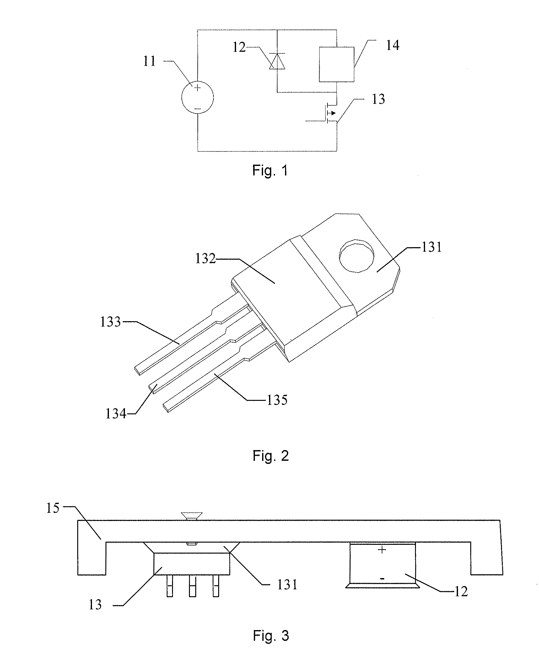
As the switching device and the free-wheeling diode 12 can continuously radiate heat when normally working, if overheating condition occurs, the working performance of the device may be affected, the working life of the device may be reduced, and even the fault of burning the device may occur when getting more serious; thereby, the normal work of the circuit is directly affected by the heat radiation of the free-wheeling diode 12.
However, the above switching tube 13 only considers the heat radiation performance of the switching device 13; the free-wheeling diode 12 is connected with the drain electrode 134 of the switching tube 13 via a welding mode, and is relatively far away from a heat radiating device; in addition, because of diodes with pins and soldering process, the cost is higher; the heat radiation effect is poor as the diode which is taken as one of heating sources is far away from the radiating device.
Additionally, the technology of adopting soldering or butt-welding process to implement connection is relatively complex, and is easy to cause virtual welding and leakage welding; the assembling and disassembling operations are complex.
No effective solution has been put forward at present aiming at the problem that the free-wheeling diodes in the prior art have poor heat radiation effect.

Method used


Image

  • Switching Device with Free-Wheeling Diode
  • Switching Device with Free-Wheeling Diode
  • Switching Device with Free-Wheeling Diode

Examples


Embodiment Construction

[0026]It should note that, the embodiments in the application and the characteristics of the embodiments can be mutually combined without conflict. The disclosure is described below in details with reference to the drawings and embodiments.

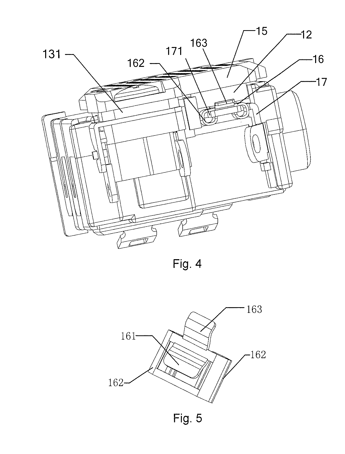
[0027]The circuit connection relationship adopted by the switching device with the free-wheeling diode in the embodiment of the disclosure is consistent with the circuit diagram of FIG. 1; the circuit connection is not modified, and the adopted switching tube is a TO-packaged switching tube, such as a Metal Oxide Semiconductor Field Effect Transistor (MOSFET). The drain electrode of the MOSFET is electrically connected with the heat radiating substrate. The free-wheeling diode 12 adopted in the embodiment of the disclosure is a compression joint type diode; the anode end face of the compression joint type diode is directly abutted against on the heat radiating component 15; the cooling fins are generally metal materials; thereby, the disclosure no...


PUM


Abstract

The disclosure provides a switching device with a free-wheeling diode, including a switching tube; a heat radiating substrate is arranged on the drain electrode of the switching tube; the switching device further includes a heat radiating component, which is connected with the heat radiating substrate of the switching tube by contact; the free-wheeling diode is a compression joint type diode; the anode end face of the free-wheeling diode is abutted against the heat radiating component, and is electrically connected with the drain electrode of the switching tube via the heat radiating component, which not only realizes the heat radiation function by using the heat radiating component, but also realizes the electric connection to the heat radiating substrate by using the electrical conductivity of the heat radiating component.

Description

FIELD OF THE INVENTION[0001]The disclosure relates to the field of semiconductor, and in particular to a switching device with a free-wheeling diode.BACKGROUND OF THE INVENTION[0002]At present, free-wheeling diodes are arranged in all the direct-current speed-regulating semiconductor switching devices, for providing the inductive load such as a motor with discharge channels at the instant of shutting down a switching device. FIG. 1 shows a circuit diagram of a semiconductor switching device with a free-wheeling diode, as shown in FIG. 1, the cathode of a free-wheeling diode 12 should be connected to the positive input of a power supply 11, the anode of the free-wheeling diode 12 is connected with a switching device 13, namely, the free-wheeling diode 12 is connected to two ends of a inductive load 14 in parallel, for providing a discharge loop for the current of the inductive load 14 when the switching device 13 is shut down. As the switching device and the free-wheeling diode 12 ca...

Claims


Application Information

Patent Timeline
IPC IPC(8): H01L23/40H01L23/367H01L27/02H01L27/06
CPCH01L23/4006H01L27/0629H01L23/367H01L27/0255H01L2023/4087H01L2023/4031H01L2023/405H01L2023/4081H01L27/0211H01L25/18H01L2224/32245H01L2924/1203H01L2924/13091H01L23/40
Inventor CAI, YINGJIE
Owner SHANGHAI BAICHENG ELECTRONICS
Learn More