Rotating electrical machine

Pending Publication Date: 2020-10-15
DENSO CORP
View PDF6 Cites 7 Cited by
  • Summary
  • Abstract
  • Description
  • Claims
  • Application Information

AI Technical Summary

Benefits of technology

The technical effect of this patent is to reduce the risk of electrical erosion of a bearing in a rotating electrical machine. This is achieved by designing a standard structure that eliminates the concern of increasing production costs and ensures the proper operation of the rotor.

Problems solved by technology

The structure taught in the above Patent Literature 1 is, however, designed to have the dielectric layer disposed between the outer iron core and the inner iron core of the rotor, and thus is non-standard, which leads to a concern about an increase in production costs.

Method used


Image

  • Rotating electrical machine
  • Rotating electrical machine
  • Rotating electrical machine

Examples


first embodiment

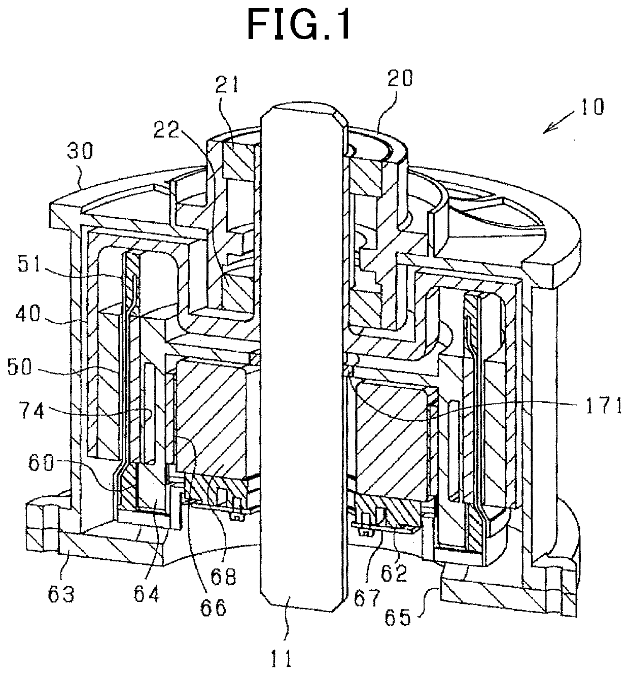
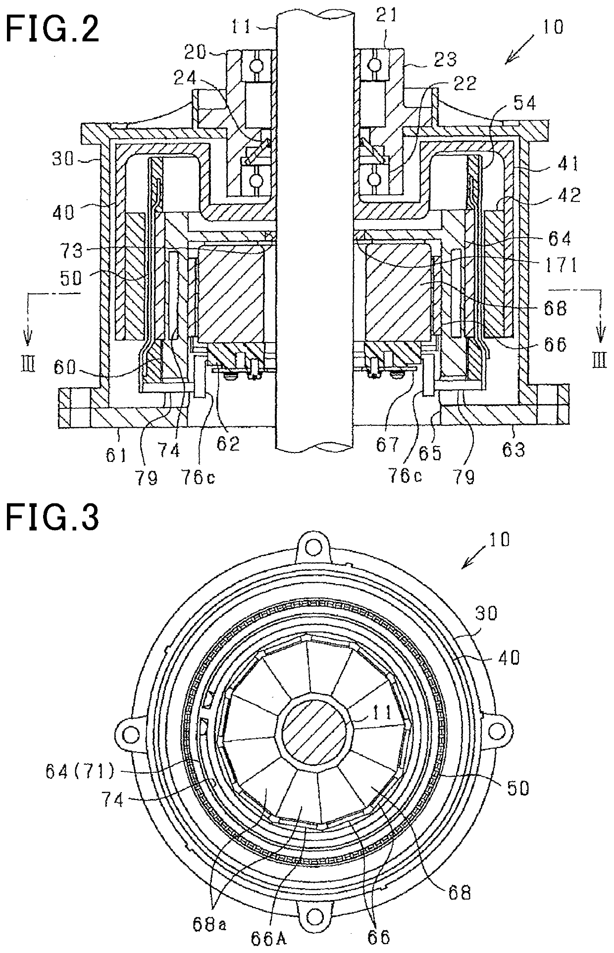
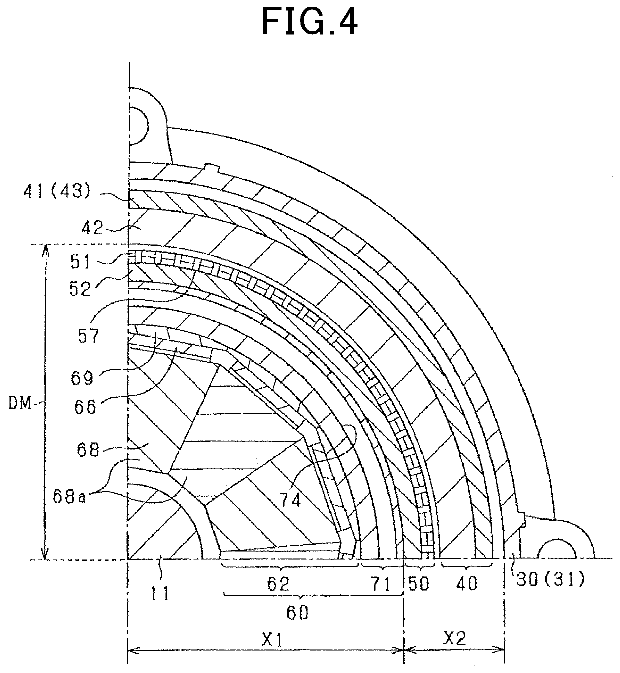
[0127]The rotating electrical machine 10 in this embodiment is a synchronous polyphase ac motor having an outer rotor structure (i.e., an outer rotating structure). The outline of the rotating electrical machine 10 is illustrated in FIGS. 1 to 5. FIG. 1 is a perspective longitudinal sectional view of the rotating electrical machine 10. FIG. 2 is a longitudinal sectional view along the rotating shaft 11 of the rotating electrical machine 10. FIG. 3 is a traverse sectional view (i.e., sectional view taken along the line III-III in FIG. 2) of the rotating electrical machine 10 perpendicular to the rotating shaft 11. FIG. 4 is a partially enlarged sectional view of FIG. 3. FIG. 5 is an exploded view of the rotating electrical machine 10. FIG. 3 omits hatching showing a section except the rotating shaft 11 for the sake of simplicity of the drawings. In the following discussion, a lengthwise direction of the rotating shaft 11 will also be referred to as an axial direction. A radial direct...

second embodiment

[0301]In this embodiment, the polar anisotropy structure of the magnet unit 42 of the rotor 40 is changed and will be described below in detail.

[0302]The magnet unit 42 is, as clearly illustrated in FIGS. 22 and 23, made using a magnet array referred to as a Halbach array. Specifically, the magnet unit 42 is equipped with the first magnets 131 and the second magnets 132. The first magnets 131 have a magnetization direction (i.e., an orientation of a magnetization vector thereof) oriented in the radial direction of the magnet unit 42. The second magnets 132 have a magnetization direction (i.e., an orientation of the magnetization vector thereof) oriented in the circumferential direction of the magnet unit 42. The first magnets 131 are arrayed at a given interval away from each other in the circumferential direction. Each of the second magnets 132 is disposed between the first magnets 131 arranged adjacent each other in the circumferential direction. The first magnets 131 and the seco...

fifth modification

[0344]The conductor-to-conductor members of the stator 50 may be made of a non-magnetic material other than resin. For instance, a non-metallic material, such as SUS304 that is austenitic stainless steel.


PUM


Abstract

A rotating electrical machine includes a magnetic field-producing unit equipped with a magnet unit including a plurality of magnetic poles, and an armature which includes a multi-phase armature winding. The armature winding has conductor portions which are arranged at a given interval away from each other in a circumferential direction. The armature is designed to have conductor-to-conductor members arranged between the conductor portions in the circumferential direction. The armature may alternatively be designed not to have the conductor-to-conductor members disposed between the conductor portions in the circumferential direction. The magnet unit is magnetically oriented to have an easy axis of magnetization which is directed in a region close to a d-axis that is a center of a magnetic pole to be more parallel to the d-axis than that in a region close to a q-axis that is a boundary between magnetic poles.

Description

CROSS REFERENCE TO RELATED DOCUMENTS[0001]The present application claims the benefit of priority of Japanese Patent Application Nos. 2017-255056 filed on Dec. 28, 2017, 2017-255057 filed on Dec. 28, 2017, 2017-2555058 filed on Dec. 28, 2017, 2017-255059 filed on Dec. 28, 2017, 2017-255061 filed on Dec. 28, 2017, 2017-255062 filed on Dec. 28, 2017, 2017-255063 filed on Dec. 28, 2017, 2017-255068 filed on Dec. 28, 2017, 2017-255070 filed on Dec. 28, 2017, and 2018-164840 filed on Sep. 3, 2018.TECHNICAL FIELD[0002]This disclosure generally relates to a rotating electrical machine.BACKGROUND ART[0003]Rotating electrical machines mounted in vehicles are generally known which include a rotor equipped with permanent magnets and a stator equipped with a multi-phase stator winding. Control systems for such a type of electrical rotating machines are also known which control excitation of the stator winding in a switching control mode.[0004]Rotating electrical machines have a risk of electrica...

Claims


Application Information

Patent Timeline
IPC IPC(8): H02K1/27H02K7/08H02K5/04H02K7/00
CPCH02K7/08H02K5/04H02K7/003H02K1/2786H02K3/04H02K21/12H02K21/22H02K11/33H02K3/34H02K1/2791
Inventor TAKAHASHI, YUKI
Owner DENSO CORP
Why Eureka
Try Eureka