Noise reduction structure for solenoid assembly

Inactive Publication Date: 2006-08-24
KYOCERA DOCUMENT SOLUTIONS INC
View PDF3 Cites 0 Cited by
  • Summary
  • Abstract
  • Description
  • Claims
  • Application Information

AI Technical Summary

Benefits of technology

[0013] In view of the above circumstances, it is an object of the present invention to provide a noise reduction structure for a solenoid assembly which can maximally suppress noise in connection with driving of the solenoid valve while suppressing increase in production cost.
[0014] According to an aspect of the present invention, in an apparatus having an apparatus body provided with a solenoid assembly including a flapper designed to be changed in posture between an electromagnetically attracted posture where a solenoid is magnetized to thereby attract the flapper electromagnetically to the solenoid and a release posture where the solenoid is demagnetized to thereby move the flapper back by given biasing means and stop it by contact with a given stopper, there is provided a noise reduction structure for reducing hitting sound of the flapper relative to the stopper in connection with the postural change from the an electromagnetically attracted posture to the release posture. The solenoid assembly is mounted to a solenoid-mounting plate fixed to a frame of said apparatus body. The stopper is provided in the frame in an integrated manner.

Problems solved by technology

Such hitting sound is likely to become the cause of noise in a quiet business office.
This increases the number of components and a process time for assembling to cause a problem about increase in production cost.
Thus, when the flapper hits the stopper, a mechanical shock during the hitting is likely to cause resonance in the support plate even if a sound-absorbing material is attached to a hit surface of the stopper, to cause a problem about difficulty in effectively reducing noise.

Method used


Image

  • Noise reduction structure for solenoid assembly
  • Noise reduction structure for solenoid assembly
  • Noise reduction structure for solenoid assembly

Examples


Embodiment Construction

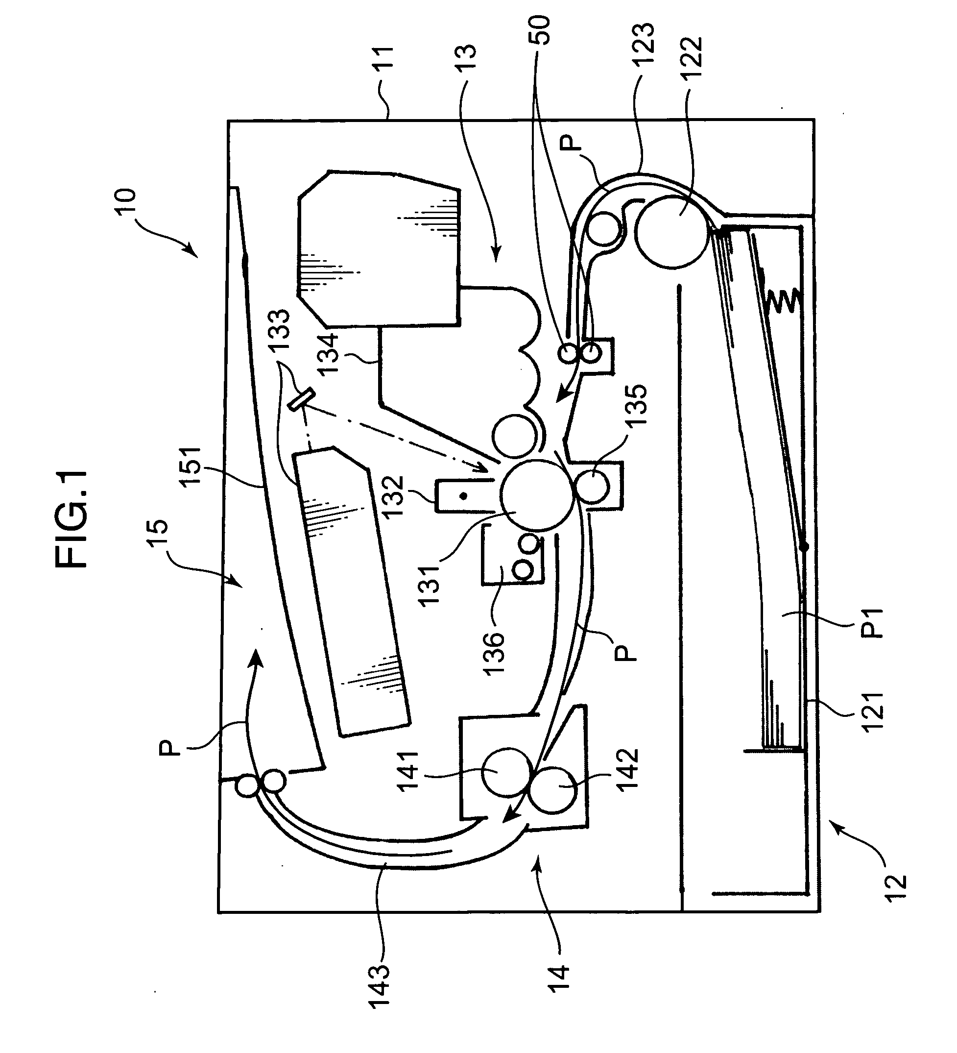
[0023]FIG. 1 is an explanatory sectional front view showing an internal structure of a printer employing a noise reduction structure for a solenoid assembly, according to one embodiment of the present invention. As shown in FIG. 1, the printer (image forming apparatus) 10 comprises an apparatus body 11 which houses a sheet storage section 12 for storing a sheet stack P1 to be subjected to a printing process, an image forming section 13 for performing an image forming process including a transfer process to sheets P picked up one-by-one from the sheet stack P1 stored in the sheet storage section 12, and a fixing section 14 for performing a fixing process to the sheet P after being subjected to the transfer process through the image forming section 13. The printer 10 further includes a sheet ejection section 15 provided at a top portion of the apparatus body 11 to receive the sheet P after being subjected to the fixing process through the fixing section 14.

[0024] The sheet storage se...


PUM


Abstract

A printer (10) has a body (11) with a solenoid assembly that includes a swingable plate (42). The swingable plate (42) can change posture between an engaged posture (S2), where the swingable plate (42) is electromagnetically attracted to a solenoid (412) and an engagement release posture (S1), where the solenoid (412) is demagnetized so that the swingable plate (42) is moved back by a coil spring (43) to perform a given operation. A noise reduction structure reduces a hitting sound of the swingable plate (42) relative to a stopper in connection with the change from the engaged posture (S2) to the engagement release posture (S1). In the noise reduction structure, the solenoid assembly is mounted to a drive plate (30) fixed to a frame of the body (11), and a positioning protrusion (212b) integrated with a 3-dimensional frame (20) is used as the stopper.

Description

BACKGROUND OF THE INVENTION [0001] 1. Field of the Invention [0002] The present invention relates to a noise reduction structure for reducing operation noise of a solenoid assembly housed in an apparatus body of a given apparatus, and more particularly to a noise reduction structure for a solenoid assembly, suitable for application to an image forming apparatus. [0003] 2. Description of the Related Art [0004] Typically, a solenoid assembly comprises a core, a solenoid wound around the core, and a flapper adapted to be electromagnetically attracted to the core when the solenoid is magnetized in response to current supply thereto, and released from the electromagnetic attraction when the solenoid is demagnetized in response to stopping the current supply. The flapper is supported in a rotatable manner around a given support shaft, and an end of the flapper disposed in opposed relation to the core is biased in a direction away from the core by given biasing means. In this connection, a...

Claims


Application Information

Patent Timeline
IPC IPC(8): B41J11/24
CPCB41J29/02B41J29/10
Inventor ISHII
Owner KYOCERA DOCUMENT SOLUTIONS INC
Why Eureka
Try Eureka