CVD apparatus, method of manufacturing susceptor using the CVD apparatus, and susceptor

Inactive Publication Date: 2014-09-04
TOYO TANSO KK
View PDF1 Cites 2 Cited by
  • Summary
  • Abstract
  • Description
  • Claims
  • Application Information

AI Technical Summary

Benefits of technology

The present invention can improve the quality and productivity of susceptors without increasing production cost or size of the apparatus.

Problems solved by technology

This method, however, has the following problems.
As a consequence, chipping or cracking occurs in the wafer.
In the worst case, for example, the problem arises that the wafer comes out of the recess.
Another problem has been that color unevenness occurs because of unevenness in the film thickness.
Moreover, it requires additional drive means, for example, for operating the rotation support rod, leading to other problems such as increase in production cost of the CVD apparatus and increase in size of the CVD apparatus.

Method used


Image

  • CVD apparatus, method of manufacturing susceptor using the CVD apparatus, and susceptor
  • CVD apparatus, method of manufacturing susceptor using the CVD apparatus, and susceptor
  • CVD apparatus, method of manufacturing susceptor using the CVD apparatus, and susceptor

Examples


embodiment 1

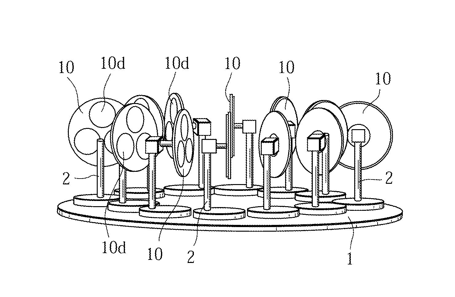
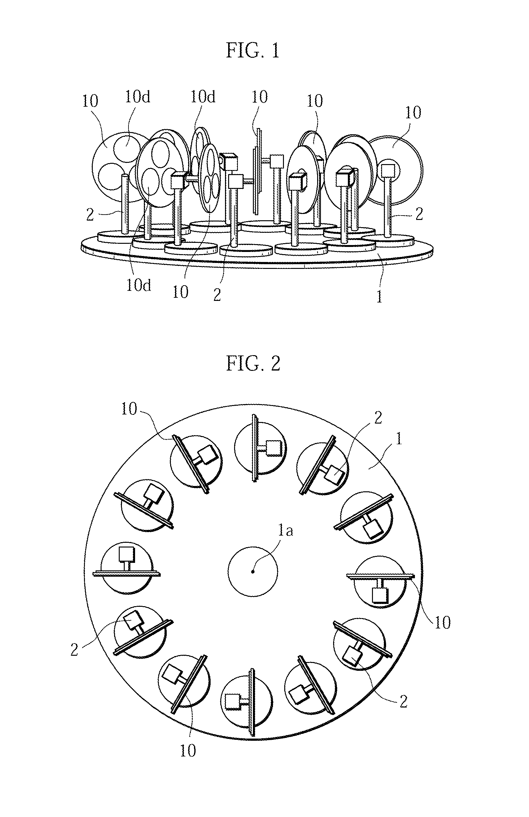
[0048]As illustrated in FIGS. 1 and 2, a CVD apparatus of the present invention has a disk-shaped rotation table 1 that rotates when forming a SiC film, and a plurality of film forming jigs 2 disposed near the outer periphery of the rotation table 1. It is desirable that these film forming jigs 2 be disposed so as to be equidistant from the center of the apparatus (i.e., the center 1a of the rotation table 1). The reason is as follows. The center of the CVD apparatus and the peripheral portion thereof have different distances from the source gas supply unit. However, when the film forming jigs 2 are disposed so as to be equidistant from the center of the apparatus, the carbonaceous substrates 10 that are attached to the film forming jigs 2 are also disposed so as to be equidistant from the center of the apparatus accordingly. Therefore, the difference in the distance from the source gas supply unit to the carbonaceous substrates 10, which depends on the arrangement positions of the ...

embodiment 2

[0056]Fabrication of the susceptor provided with the masking portion is described in the above embodiment 1. In contrast, described in this embodiment 2 is fabrication of a susceptor provided with no masking portion.

[0057]As illustrated in FIG. 6, a carbonaceous substrate 10 used with a CVD apparatus according to this embodiment 2 is provided, in a rear surface, with two recessed portions 30 and 31 that are each configured similarly to the masking portion (recessed portion) 20.

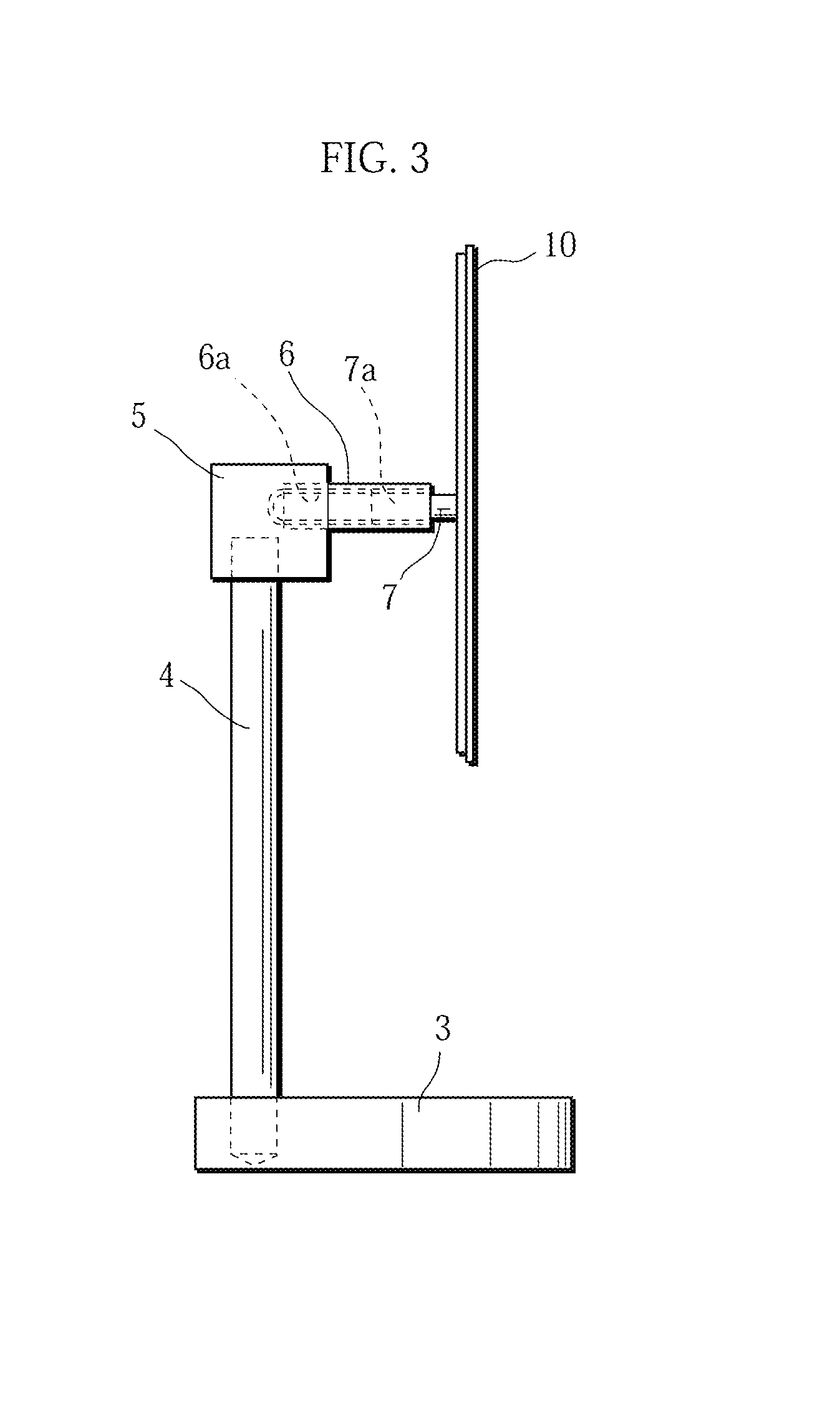
[0058]Upon film formation processing, a masking jig 7 is screw-fitted to the recessed portion 30 and is fitted to a film forming jig 2. The carbonaceous substrate 10 is thus supported in a standing posture, in which state the film formation processing is carried out. A SiC film is accordingly formed on the surface except for the recessed portion 30. Subsequently, the masking jig 7 is screw-fitted to the recessed portion 31 and is fitted to the film forming jig 2. The carbonaceous substrate 10 is thus supported...

example 1

[0065]Using the CVD apparatus according to the embodiment 1 of the present invention, a susceptor was fabricated by forming a film on a carbonaceous substrate in a disk shape having 465 mm in diameter and 16 mm in thickness. The susceptor fabricated in this manner is hereinafter referred to as a present invention susceptor A1. The experiment conditions (film formation conditions) were as follows.[0066]Experiment Conditions[0067]Pressure in the apparatus: 0.1 Torr to 760 Torr[0068]Temperature in a furnace: 1150° C. to 1500° C.[0069]Introduced gas: CH3SiCl3 (methyltrichlorosilan) and hydrogen gas as carrier gas[0070]Film thickness of the SiC film: 40 μm to 60 μm


PUM


Abstract

A masking portion (recessed portion) 20 is provided at the center of a rear surface of a carbonaceous substrate 10. The masking portion 20 includes a first bore portion 20a and a second bore portion 20b. The first bore portion 20a has an inner wall in which a female screw portion 21 is formed. A male screw portion 7a of a masking jig 7 is screw-fitted to the female screw portion 21. The masking jig 7 is fixed to a film forming jig 2. The carbonaceous substrate is thus supported in a standing posture, and the carbonaceous substrate is provided, on a surface, with a firm such as a SiC film or a TaC film except for the recessed portion by introducing gas into the apparatus in this supported state.

Description

TECHNICAL FIELD[0001]The present invention relates to a CVD apparatus for forming a film such as a SiC film or a TaC film on an entire surface of a carbonaceous substrate, a method of manufacturing a susceptor using the CVD apparatus, and a susceptor fabricated by this manufacturing method.BACKGROUND ART[0002]A susceptor used for semiconductor epitaxial growth, for example, is made of a material in which a coating layer of a SiC, a TaC, or the like is formed on a surface of a carbonaceous substrate. For example, the formation of the SiC film on the carbonaceous substrate surface is usually carried out by a CVD (chemical vapor deposition) technique, in which SiC is deposited on the carbonaceous substrate surface directly by causing a halogenated organic silicon compound containing a carbon source, such as hydrocarbon, to undergo a thermal decomposition reaction in a reductive gas flow. The formed SiC film needs to be formed in an extremely dense and uniform layer without any pin hole...

Claims


Application Information

Patent Timeline
IPC IPC(8): C23C16/04C23C16/32C30B35/00
CPCC30B35/00C23C16/325C23C16/042C04B41/5057C23C16/4404C04B41/5059C04B41/009C23C16/4588C04B41/87C04B35/52C04B41/4531C04B41/4572
Inventor KITA, MASAAKIKUBOTA, TAKESHIHIRANO, HIROYUKI
Owner TOYO TANSO KK
Why Eureka
Try Eureka