Carriage driving apparatus and image forming apparatus

Inactive Publication Date: 2007-06-28
BROTHER KOGYO KK
View PDF1 Cites 0 Cited by
  • Summary
  • Abstract
  • Description
  • Claims
  • Application Information

AI Technical Summary

Benefits of technology

[0008] However, it is the present state that the guide member is formed by bending a single plate member. Therefore, when the mounting member is configured so as to extend the mounting member, the guide member should be processed from a great plate member according to the increased mounting member. Therefore, a plate member having a size greater than the size of the plate member before the mounting member is extended in the direction apart from the carriage is needed, which entails increased material cost and time-consuming labor. Accordingly, the production cost for the carriage driving apparatus is increased, thus unpreferable.
[0009] In order to solve the problem described above, an object is to realize a configuration in which the mounting position of the encoder strip is apart from the guide position of the carriage, while preventing the production cost for the carriage driving apparatus from increasing.
[0013] Specifically, as for the first guide member, the portion for supporting the encoder strip does not have to be formed upon forming the first guide member by bending a single plate member, whereby the material cost as the plate member can be held down.

Problems solved by technology

This is because, when the case in which the carriage driving apparatus is provided to an image forming apparatus is taken as an example, the encoder strip is liable to be stained by ink ejected from an ink head mounted to the carriage and / or lubricant applied to the guide members.
In addition, the encoder may be disposed upward of the guide position up to the remote region where the encoder is barely able to precisely detect in the primary scanning direction the uppermost displacement based on posture change of the carriage in use.
Therefore, a plate member having a size greater than the size of the plate member before the mounting member is extended in the direction apart from the carriage is needed, which entails increased material cost and time-consuming labor.
Accordingly, the production cost for the carriage driving apparatus is increased, thus unpreferable.

Method used


Image

  • Carriage driving apparatus and image forming apparatus
  • Carriage driving apparatus and image forming apparatus
  • Carriage driving apparatus and image forming apparatus

Examples


Embodiment Construction

[0020] An embodiment will be described below with reference to drawings.

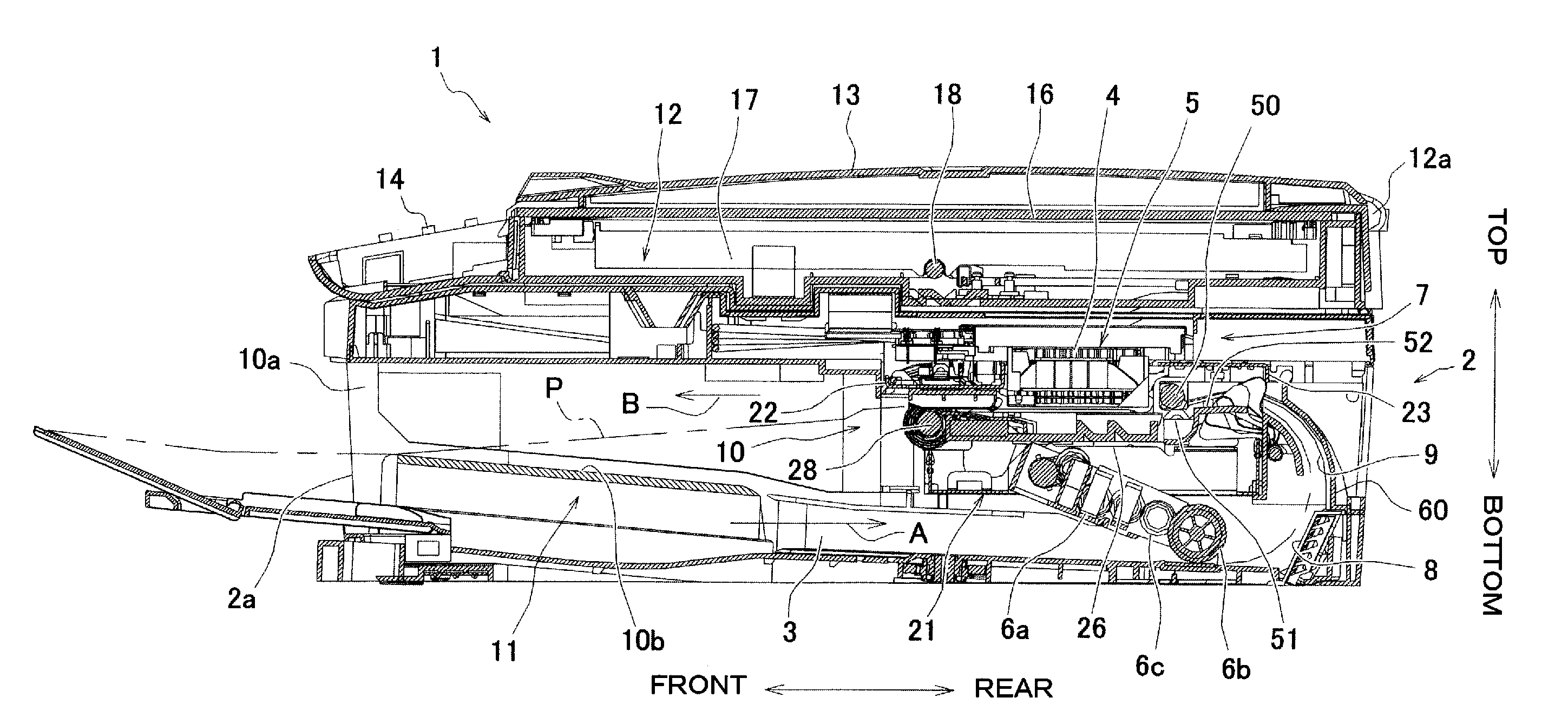
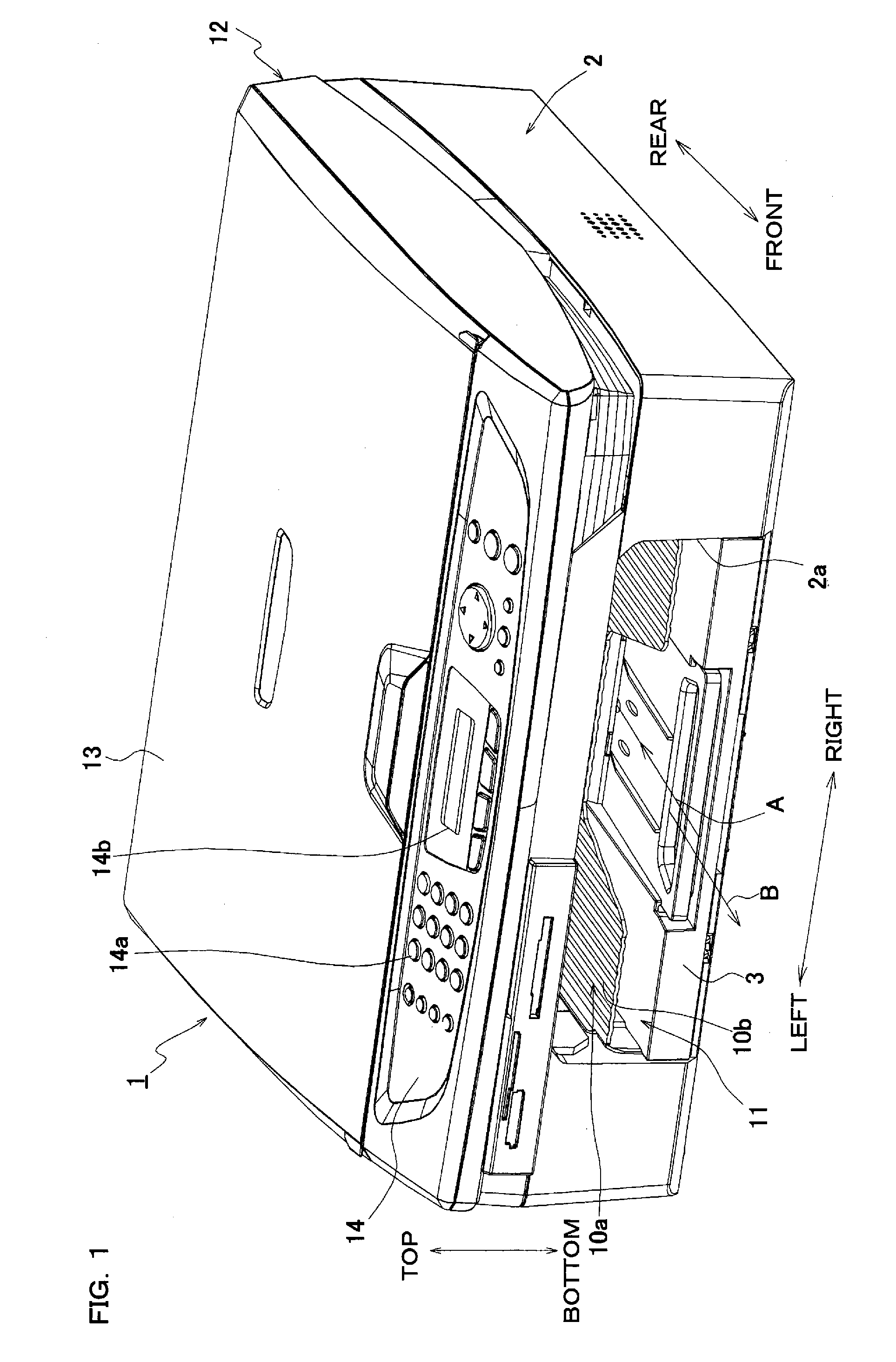
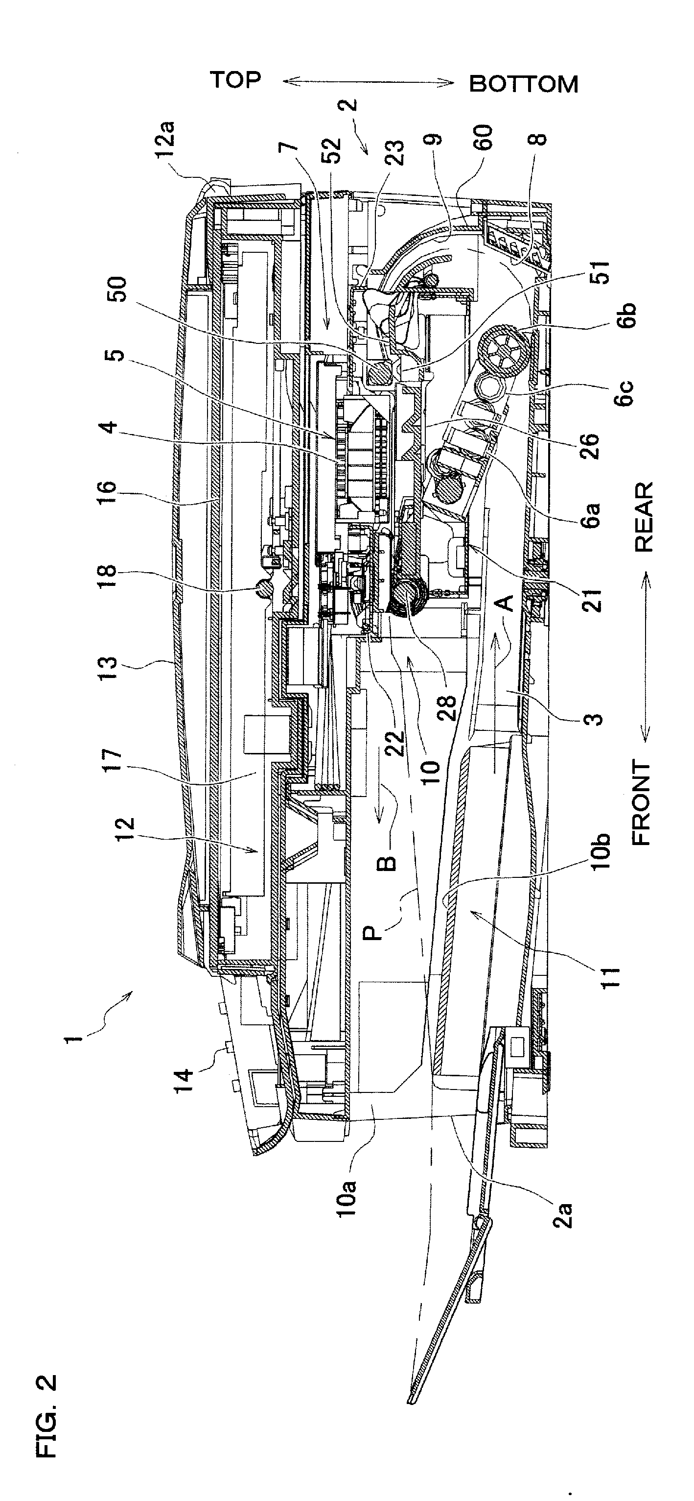
[0021]FIG. 1 is a perspective view showing an appearance of a composite machine 1 serving as an image forming apparatus according to one embodiment, and FIG. 2 is its side sectional view. In the following explanation, the top-to-bottom direction is expressed on the basis of the normal use state (the state shown in FIG. 1) of the composite machine 1, the front-to-rear direction is expressed such that the side where an operation panel section 14 described later is provided is defined as the near (front) side, and right-to-left direction is expressed as the composite machine 1 is viewed from the near side (from the front).

[0022] The composite machine 1 has a printer function, scanner function, color copy function, facsimile function, etc. As shown in FIGS. 1 and 2, an image reading device 12 used for reading a document is mounted at the top portion of a housing 2 made of a synthetic resin.

[0023] The image readin...


PUM


Abstract

There is provided a carriage driving apparatus having a first guide member and a second guide member that extend in parallel and are adjacent to each other, and a carriage disposed between the first guide member and the second guide member that queue side by side, the carriage being capable of reciprocative movement in a extending direction of the guide members by being guided by the guide members. The carriage driving apparatus including a detection strip arranged along the extending direction for detecting the position of the carriage in the extending direction, and first extending portion and second extending portion mounted respectively at one end and another end of the first guide member and extending respectively from each end so as to be perpendicular to the extending direction and a queuing direction of the guide members, the extending portions supporting the detection strip.

Description

CROSS-REFERENCE OF RELATED APPLICATION [0001] This nonprovisional application claims priority under 35 U.S.C. §119(a) on Patent Application No. 2005-380148 in Japan on Dec. 28, 2005, the entire contents of which are hereby incorporated by reference. BACKGROUND [0002] The present invention relates to a carriage driving apparatus provided with a carriage that makes a reciprocating movement in a scanning direction. [0003] The applicant has proposed a carriage driving apparatus provided with a carriage that makes a reciprocating movement in a scanning direction in order to realize downsizing an image forming apparatus. [0004] In the carriage driving apparatus, a carriage (5) is disposed between a pair of guide members (first and second guide members 22 and 23) extending respectively in the same direction, wherein the carriage makes a reciprocating movement in the direction of extending the guide members, defined as the scanning direction (see Japanese Patent Application Laid-Open No. 20...

Claims


Application Information

Patent Timeline
IPC IPC(8): B41J23/00
CPCB41J19/005B41J19/207
Inventor TAMAKI, SHUICHISAMOTO, KENJI
Owner BROTHER KOGYO KK
Why Eureka
Try Eureka