Eureka AIR delivers breakthrough ideas for toughest innovation challenges, trusted by R&D personnel around the world.

Induction cooktop system

a technology of induction cooktop and cooktop plate, which is applied in the direction of induction heating, climate sustainability, sustainable buildings, etc., can solve the problems of inability to meet the needs of users, waste of time by users, waste of food, etc., and achieve the effect of reducing the time to cook meals, limiting waste throughout the cooking process, and reducing was

Active Publication Date: 2020-09-17
BONBOWL LLC
View PDF0 Cites 5 Cited by
  • Summary
  • Abstract
  • Description
  • Claims
  • Application Information

AI Technical Summary

Benefits of technology

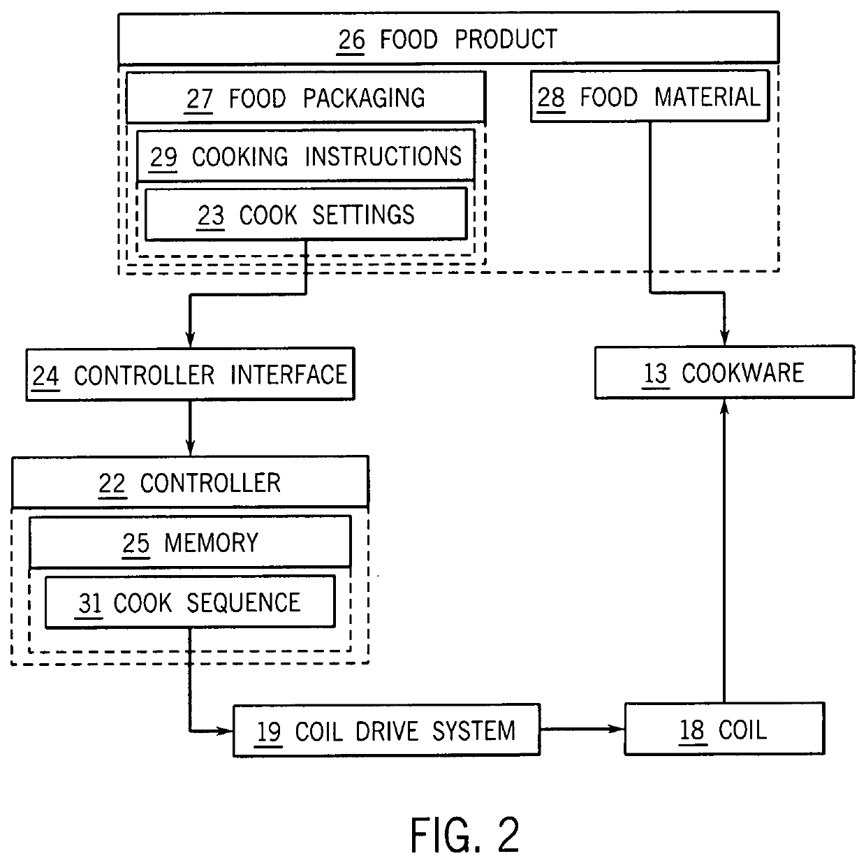
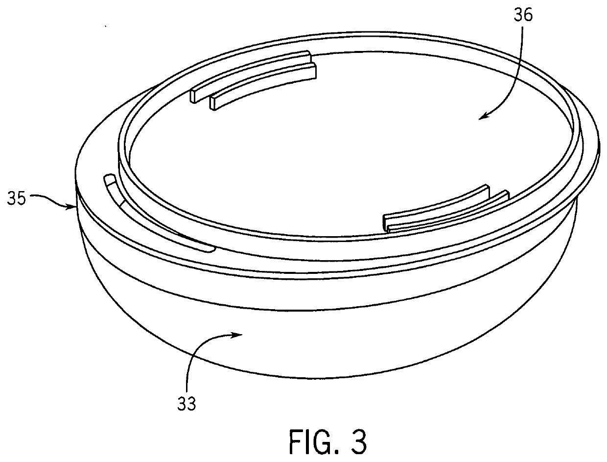
This patent describes an induction cooking system that creates a better user experience, reduces cooking time and reduces waste during cleanup. The system includes an induction cooking appliance with a coil underneath the cooktop surface and custom cookware. The custom cookware has an inner shell made of metallic material to heat the food and an outer shell made of thermally insulating material that is transparent to magnetic flux. The outer shell has an aperture for the temperature sensor to monitor the cooking process. This system creates a more desirable user experience, reduces cooking time, and limits waste during the cooking and cleanup process.

Problems solved by technology

Due to inconsistencies in size, shape, power, and other features involved in a system of induction cooking, food is often improperly cooked.
This can lead to waste of food, waste of energy by the device, or waste of time by the user.
While various attempts have been made to address these inconsistencies, such attempts have not proven satisfactory as unduly complex and complicated, even utilizing wireless communications.

Method used


Image

  • Induction cooktop system
  • Induction cooktop system
  • Induction cooktop system

Examples


Embodiment Construction

Introduction

[0019]As previously introduced, induction cooking utilizes an electric current passed through a coiled copper wire underneath a cooking surface, which creates a magnetic current throughout the cooking pan to produce heat. Due to inconsistencies in size, shape, power, and other features involved in a system of induction cooking, food is often improperly cooked. This can lead to waste of food, waste of energy by the device, or waste of time by the user.

[0020]For example, most cookware is designed to be used on a gas or electric stovetop, and is not optimized specifically for induction cooktops. Additionally, the food is usually cooked in a container that is specifically designed for cooking purposes and not for eating, which creates extra dirty dishes to clean after the user eats the meal, or extra waste that the user must dispose of. After cooking a meal, the cookware is oftentimes too hot to touch and requires the user to insulate their hands with a hot mitt or similar s...


PUM


Abstract

An induction cooking system in accordance with the principals of the present invention includes an induction cooking appliance and custom cookware. The induction cooking appliance includes a cooktop surface, an induction heating system contained below the cooktop surface, and a temperature sensor. The temperature sensor sensing temperature above the cooktop surface. The induction heating system includes a coil positioned immediately below the cooktop surface. The coil is configured to produce an electromagnetic field when the coil is energized. The custom cookware is configured to be placed on the cooktop surface above the coil. The custom cookware includes an inner shell and an outer shell. The inner shell is comprised of a metallic material to heat a food material. The outer shell is comprised of a thermally insulative material that is substantially transparent to magnetic flux. The outer shell includes an underside configured to rest on the cooktop surface above the coil during cooking. The underside defines a thermal-insulation aperture through which the temperature sensor extends temperature sensing above the cooktop surface to the inner shell.

Description

RELATED APPLICATIONS[0001]This application claims priority from U.S. Provisional Patent Application Ser. No. 62 / 817,032, filed 12 Mar. 2019 entitled “Induction Cooktop System”, the disclosure of which is incorporated herein by this reference.FIELD OF THE INVENTION[0002]The present invention relates to induction cooktop systems.BACKGROUND OF THE INVENTION AND STATE OF THE ART[0003]Various forms of electric powered cooking systems are widely used throughout the world. Common devices include electric stoves, microwaves, ovens, toasters, and induction cooktops. Induction cooking utilizes electric currents to directly heat pots and pans through magnetic induction. Instead of using gas or an electric element transferring heat from a burner to a pot or pan via thermal conduction, induction heats the cooking vessel itself.[0004]In induction cooking an electric current is passed through a coiled copper wire underneath the cooking surface, which creates a magnetic current throughout the cooki...

Claims


Application Information

Patent Timeline
Patent Type & Authority Applications(United States)
IPC IPC(8): H05B6/12H05B6/06
CPCH05B6/062H05B6/1245H05B2213/07Y02B40/00
Inventor KOBIDA, JR., MICHAEL J.
Owner BONBOWL LLC
Why Eureka
Eureka Blog
Learn More