
System and method for determining aircraft safe taxi, takeoff, and flight readiness

a technology of safe taxi and flight readiness, applied in the field of systems and methods for determining takeoff and flight readiness of aircraft, can solve the problems of limited information obtained, inability for pilots to see the flaps of aircraft, and congestion of airport ground travel surfaces

Active Publication Date: 2020-09-17
BOREALIS TECH LTD
View PDF10 Cites 7 Cited by
  • Summary
  • Abstract
  • Description
  • Claims
  • Application Information

AI Technical Summary

Benefits of technology

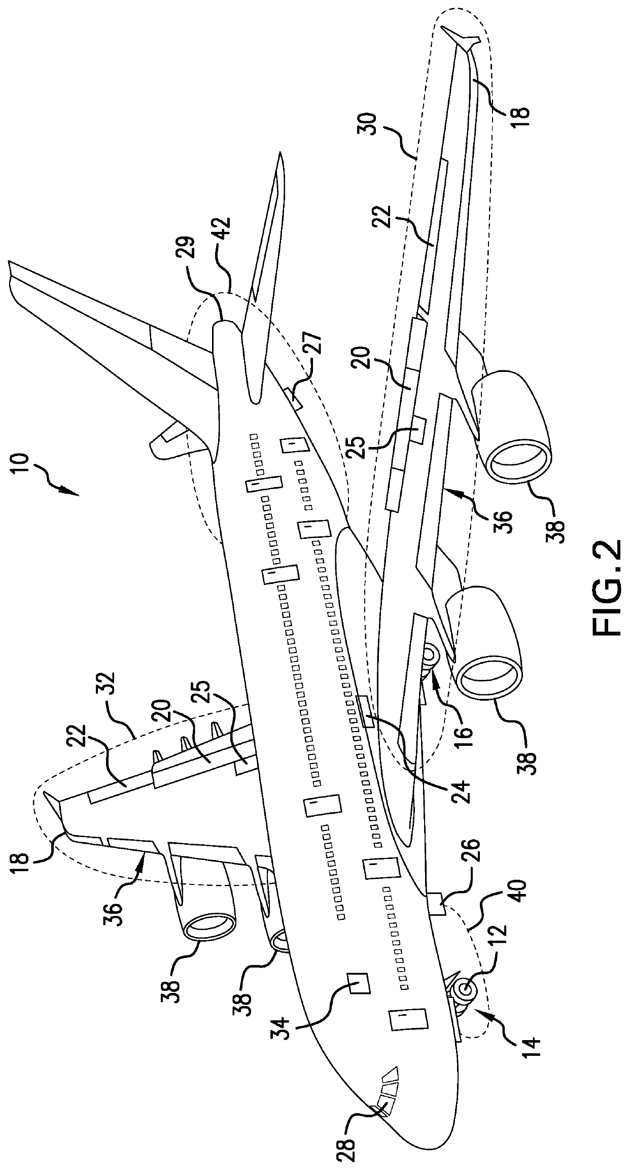
The present invention is about an integrated monitoring system and method that allows pilots and cockpit crews to observe the external structures and surfaces of an aircraft, including the flaps and landing gears, in real-time. This system can provide accurate information that helps ensure the aircraft is ready for takeoff and flight, avoiding tail strikes and runway excursions. The monitoring system includes a scanning LiDAR device or a combination of LiDAR and a camera mounted on the exterior of the aircraft to collect data, which is then transmitted to an intelligent processing system to generate a visual display for the pilot. This invention enhances the safety of aircraft takeoff and airport operations.

Problems solved by technology

Airport ground travel surfaces can be very congested places at today's airport terminals.
While potentially helpful in avoiding collisions during ground maneuvers within an airport ramp area, there may be limitations to the information obtained, especially during low visibility weather conditions.
It is not presently possible for a pilot actually to see the aircraft's flaps to verify flap positions.
Improper flaps settings and / or settings that cause misaligned flaps may not be detected by current warning systems and may not activate a warning.
Takeoff of the aircraft under these circumstances could have serious adverse consequences.
The pilot and crew were faced with conflicting information, and they could not visually verify which condition was accurate.

Method used


Image

  • System and method for determining aircraft safe taxi, takeoff, and flight readiness
  • System and method for determining aircraft safe taxi, takeoff, and flight readiness

Examples


Embodiment Construction

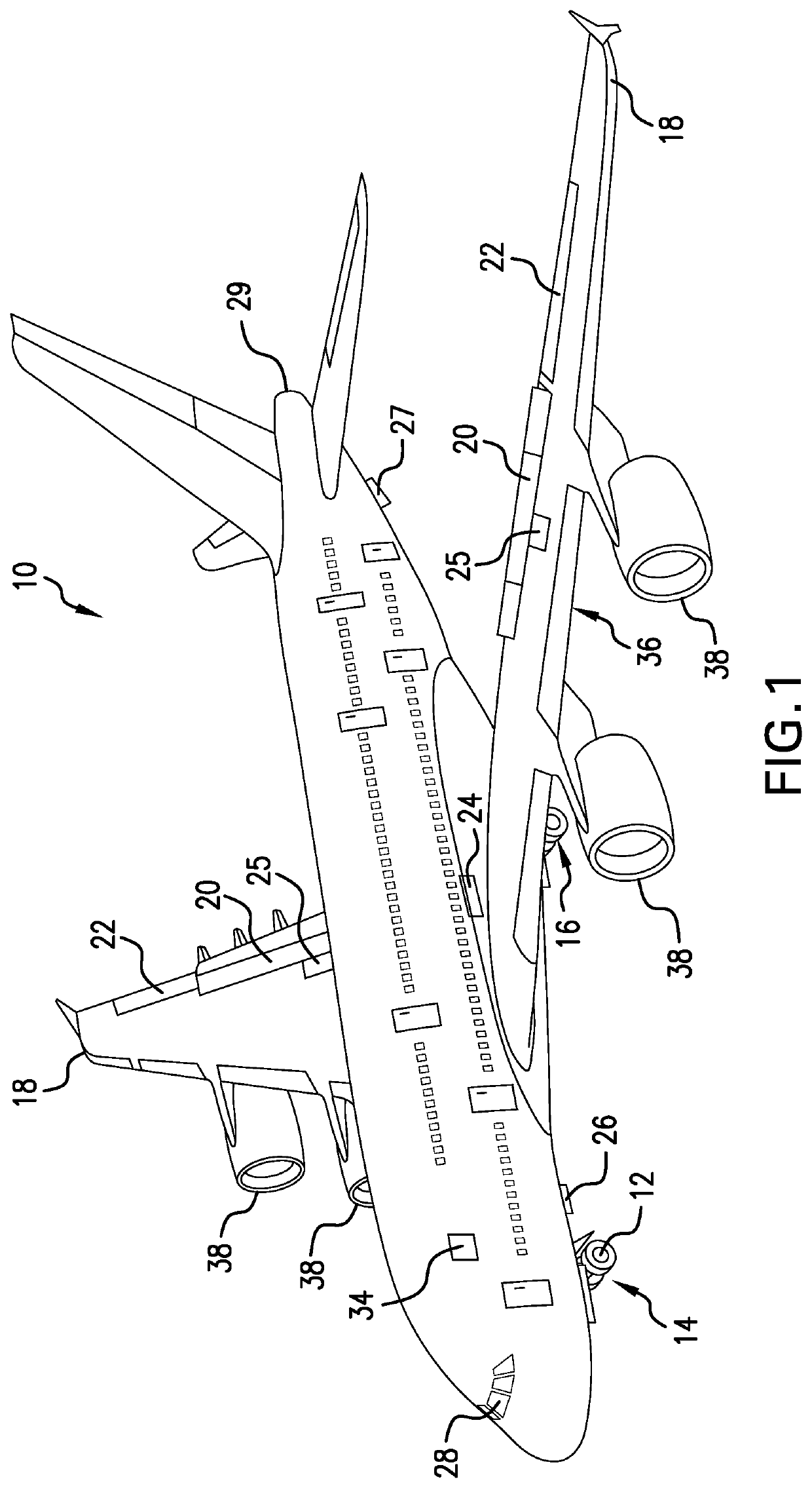
[0024]The movement of aircraft into, out of, and within congested airport ramp surface areas safely while avoiding collisions and other adverse ground incidents is critical to maintaining the safety of the aircraft, as well as that of all persons and vehicles in this airport area. Monitoring systems may improve situational awareness as aircraft pilots and flight crew are driving an aircraft during ramp ground surface operations by providing a clear view of the spatial environment around the moving aircraft from the cockpit, as well as from ramp and ground control perspectives. Available monitoring systems, however, have focused primarily on the ground environment around an aircraft's exterior and the relative locations of adjacent aircraft, ground vehicles and personnel, and ground structures. The monitoring system of the present invention provides a targeted view of specific exterior structures on an aircraft, namely the flaps, the landing gears, and the tail, that must be position...


PUM


Abstract

A monitoring system and method are provided for real time monitoring of flaps, landing gears, or tail skids to determine safe taxi, takeoff, and flight readiness. Monitoring units, including scanning LiDAR devices combined with cameras or sensors, mounted in aircraft exterior locations produce a stream of meshed data that is securely transmitted to a processing system to generate a real time visual display of the flaps, landing gears, or tail skid for communication to aircraft pilots to ensure safe aircraft taxi, takeoff, and flight readiness. Actual flap position alignment with optimal flap setting, proper retraction and extension positions of landing gears, and tail skid condition is ensured. Safety of aircraft taxi, takeoff and flight and airport operations are improved when the present system and method are used to prevent incidents related to misaligned flaps and improperly positioned landing gears or tail skids.

Description

PRIORITY CLAIM[0001]This application claims priority from U.S. Provisional Patent Application No. 62 / 816,868, filed 11 Mar. 2020, the entire disclosure of which is fully incorporated herein in its entirety.FIELD OF THE INVENTION[0002]The present invention relates generally to systems and methods for determining takeoff and flight readiness of aircraft and specifically to a monitoring system and method providing visual confirmation to an aircraft cockpit that aircraft external components are in safe taxi, takeoff, and flight ready positions.BACKGROUND OF THE INVENTION[0003]Airport ground travel surfaces can be very congested places at today's airport terminals. Multiple aircraft are simultaneously arriving and departing, ground-based service and support vehicles and personnel are servicing parked aircraft, and ground crews are directing the arriving and departing aircraft into and out of gates. The avoidance of adverse ground incidents in these areas requires careful monitoring and c...

Claims


Application Information

Patent Timeline
Patent Type & Authority Applications(United States)
IPC IPC(8): B64D45/00B64D43/00B64D47/08G08G5/06G08G5/00
CPCB64D43/00B64D45/0005G08G5/06G08G5/0095B64D2045/0075B64D47/08B64C25/405G08G5/065G08G5/0021Y02T50/80B64F1/002B64F1/22
Inventor FERRELL, STUART MARKREED, WILLIAM T.VANA, JANCOX, ISAIAH W.
Owner BOREALIS TECH LTD
Learn More