Method of adjusting texture coordinates based on control regions in a panoramic image

a technology of texture coordinates and control regions, applied in the field of panoramic imaging, can solve the problems of enormous data volume that needs to be measured, and 5 doesn't guarantee the achievement of optimal results, so as to facilitate the generation of panoramic images, minimize the mismatch image defect, and improve the effect of image quality

Active Publication Date: 2020-09-10
ASPEED TECH
View PDF0 Cites 4 Cited by
  • Summary
  • Abstract
  • Description
  • Claims
  • Application Information

AI Technical Summary

Benefits of technology

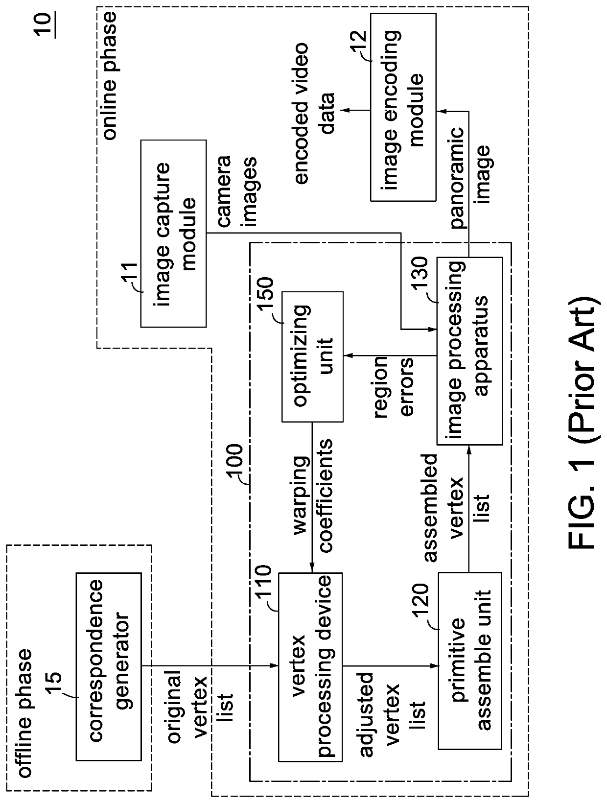
The invention provides a way to adjust texture coordinates in a panoramic image by using control regions. This technique helps create better quality panoramic images and reduces image defects caused by misaligned camera centers.

Problems solved by technology

In addition, if there are ten different current warping coefficients for each overlap region, there would be 1012 combinations in total for the twelve overlap regions and thus enormous data volume needs to be measured.
The method of FIG. 5 doesn't guarantee that an optimal result would be achieved within a predefined number of loops.

Method used


Image

  • Method of adjusting texture coordinates based on control regions in a panoramic image
  • Method of adjusting texture coordinates based on control regions in a panoramic image
  • Method of adjusting texture coordinates based on control regions in a panoramic image

Examples


example camera

[0055 images include, with limitation, YUV color images, RGB color images, luminance images, edge images and motion vector images. As well known in the art, an edge image can be obtained by applying an edge detection operator (such as a Canny edge detector or a Sobel operator) over a normal color image; a motion vector image can be obtained by performing motion estimation using known algorithms (such as block-matching algorithm, pixel recursive algorithm or optical flow) over two consecutive camera images (such as two top-face camera images (t0) and (t1)).

[0056]For N>1, according to the N pairs of texture coordinates, N texture mapping engines 821˜82N of the texture mapping circuit 82 texture map the texture data from the N camera images using any appropriate method (such as nearest-neighbour interpolation, bilinear interpolation or trilinear interpolation) to generate N sample values (s1˜sN) in parallel. Here, the sample value (s1˜sN) may be a luma value, a chroma value, an edge va...


PUM


Abstract

A method of adjusting texture coordinates based on control regions in a panoramic image is disclosed. The method comprises determining warping coefficients of a plurality of control regions in a panoramic image; retrieving two selected warping coefficients out of the warping coefficients for each of a plurality of camera images with respect to each vertex from a first vertex list according to two coefficient indices for each camera image in its data structure; calculating an interpolated warping coefficient for each camera image with respect to each vertex according to the two selected warping coefficients and a coefficient blending weight for each camera image in its data structure; and, calculating modified texture coordinates in each camera image for each vertex according to the interpolated warping coefficient and original texture coordinates for each camera image in its data structure to form a second vertex list.

Description

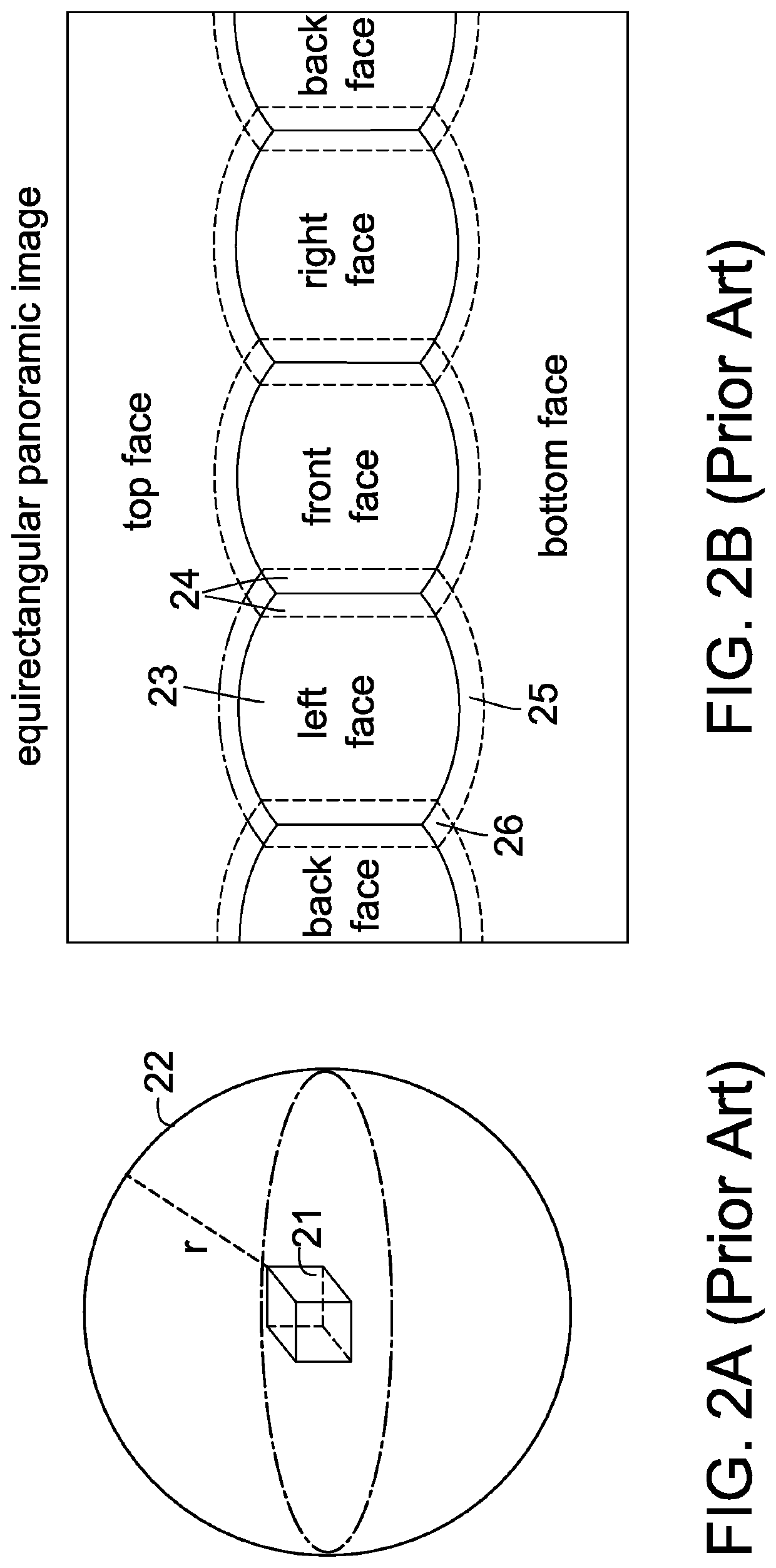
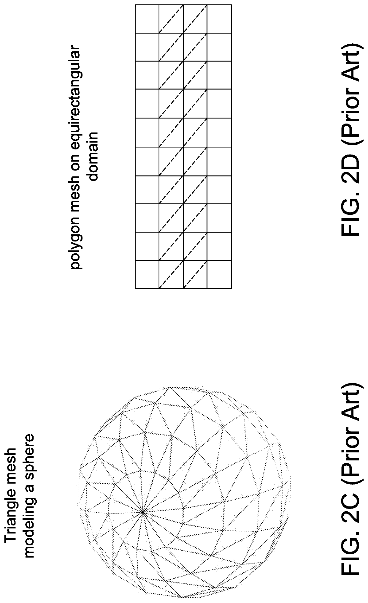
BACKGROUND OF THE INVENTIONField of the Invention[0001]The invention relates to panoramic imaging, and more particularly, to a method of adjusting texture coordinates based on control regions in a panoramic image. The invention facilitates generation of panoramic images in image processing system.Description of the Related Art[0002]360-degree panoramic images, also known as 360-degree panoramic images, full panoramic images, or spherical images, are video recordings of a real-world panorama, where the view in every direction is recorded at the same time, shot using an omnidirectional camera or a collection of cameras. A 360-degree panoramic image covers 360 degree field of view (FOV) horizontally and 180 degree vertically.[0003]An equirectangular video is a commonly projection used in 360-degree video. A common example of equirectangular projection is a standard world map, which maps the surface of the world (a sphere) onto orthogonal coordinates. That is, equirectangular projection...

Claims


Application Information

Patent Timeline
IPC IPC(8): G06T3/20H04N5/232G06T3/00G06T3/40
CPCG06T3/0012G06T3/4038G06T3/0093H04N5/23238G06T3/20H04N23/698G06T3/18G06T3/04
Inventor LU, CHUNG-YEN
Owner ASPEED TECH
Why Eureka
Try Eureka