
Vibration reduction optimization method for host system of tunnel boring machine

a technology of tunnel boring machine and host system, which is applied in the direction of mechanical equipment, shock absorbers, instruments, etc., can solve the problems of host system failure, strong impact load generation by cutter, wear and even breakage of some key parts of the tbm,

Inactive Publication Date: 2020-09-10
DALIAN UNIV OF TECH
View PDF0 Cites 5 Cited by
  • Summary
  • Abstract
  • Description
  • Claims
  • Application Information

AI Technical Summary

Benefits of technology

The patent proposes an optimization scheme for reducing the vibration of a tunnel boring machine's cutterhead system and preventing fatigue damage. This is achieved by replacing the stiffened plates with a damping alloy and adding magnetorheological dampers to the support and propulsion systems. The optimized layout model of the damping alloy replacement stiffened plates material is also proposed. The invention aims to make the TBM host system safer, reliable, and prevent accidents.

Problems solved by technology

Due to the complex TBM tunneling environment and the multi-point impact rock breaking of the TBM cutter, the cutter will generate strong impact loads during rock cutting.
This will cause the TBM host to vibrate violently, eventually causing wear and even breakage in some key parts of the TBM.
Severe load conditions cause severe vibration of the TBM host system, which in turn causes failure of the host system and affects the normal operation of the TBM.
Because the tunneling environment of TBM is very bad, although scholars have done some research on the vibration reduction optimization of TBM, there is no complete solution for the vibration reduction optimization of TBM host system.
Because the structure of the TBM host system is complex and there are many coupling factors to be considered, although some scholars have done some theoretical research to improve the vibration reduction, there are many problems, such as serious model simplification, incomplete analysis, and poor engineering applicability.
Such problems have made the research have certain limitations.

Method used


Image

  • Vibration reduction optimization method for host system of tunnel boring machine
  • Vibration reduction optimization method for host system of tunnel boring machine
  • Vibration reduction optimization method for host system of tunnel boring machine

Examples


Embodiment Construction

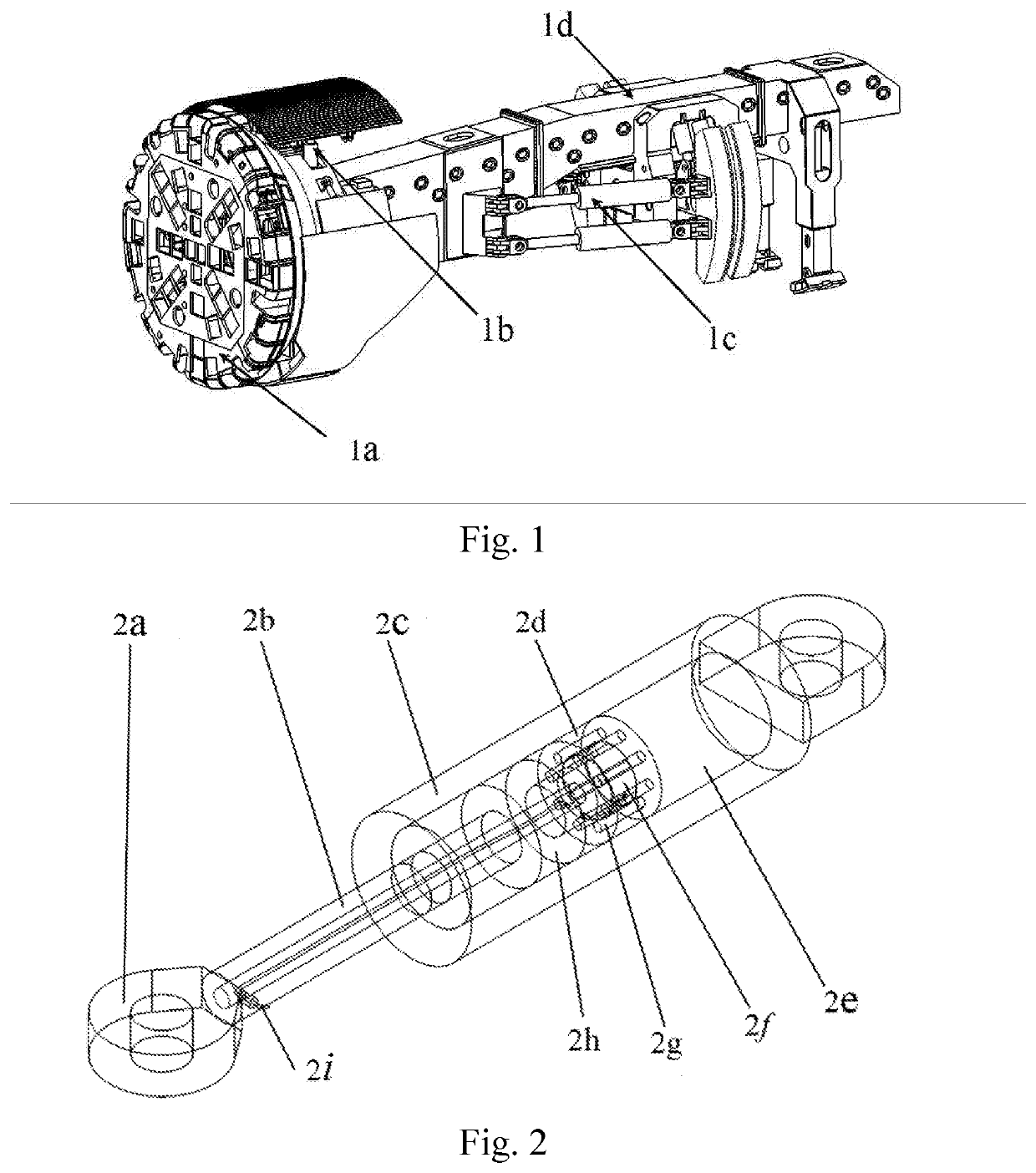
[0044]The specific embodiments of the present invention are described in detail below with reference to the accompanying drawings and technical solutions. FIG. 1 is a schematic diagram of a TBM host system of a project, including the main components such as the cutterhead system, the support system, the propulsion system and the main beam. During the work of TBM, the cutter has the characteristics of multi-point impact rock breaking. When the cutter cuts the rock, a strong impact load will be generated, which will cause the TBM to vibrate violently, eventually causing wear and even breakage of some key parts of the TBM.

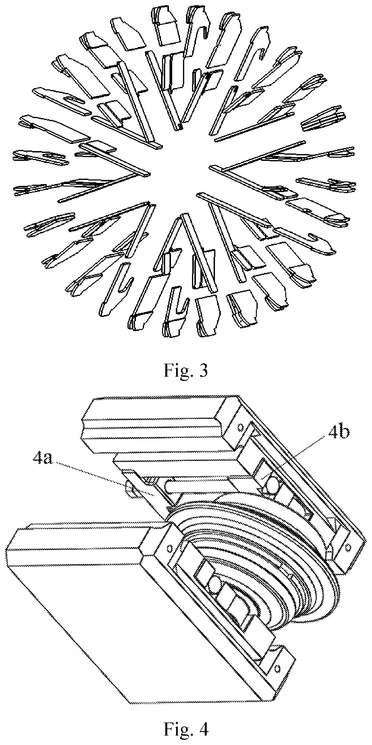
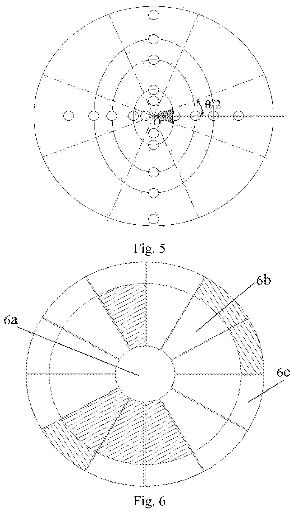
[0045]For the cutterhead system, the material replacement of the cutterhead's stiffened plates and the wedge blocks in the cutter-holder connection structure achieves the purpose of vibration reduction optimization, and the material replacement model of the cutterhead's stiffened plates and the material replacement model for wedge blocks of TBM's cutter-holder connect...


PUM


Abstract

A vibration reduction optimization method for host system of a tunnel boring machine to reduce the vibration of the host and prevent fatigue damage at the critical weak position of the TBM host system. Vibration reduction optimization of the TBM host system is achieved by using a damping alloy material to replace the cutterhead system's material and the connecting flange's material and adding a magnetorheological damper at the support system and the propulsion system. This prevents sudden incidents in the TBM host system and ensures that the TBM works safely and reliably.

Description

TECHNICAL FIELD[0001]The present invention relates to vibration reduction optimization method for host system of a tunnel boring machine (TBM), and belongs to the technical field of vibration reduction design of the TBM.BACKGROUND TECHNIQUE[0002]Tunnel boring machine (TBM) is a factory-built assembly line tunnel construction equipment integrating machine, electricity, liquid, light and gas systems. It has the advantages of fast tunneling speed and high comprehensive efficiency. It is widely used in tunnel projects such as railways, hydropower, transportation, and mines. Due to the complex TBM tunneling environment and the multi-point impact rock breaking of the TBM cutter, the cutter will generate strong impact loads during rock cutting. This will cause the TBM host to vibrate violently, eventually causing wear and even breakage in some key parts of the TBM. Therefore, how to achieve the vibration reduction optimization of the host system is particularly important. Therefore, the vi...

Claims


Application Information

Patent Timeline
Patent Type & Authority Applications(United States)
IPC IPC(8): G06F30/20E21D9/10G06F30/17
CPCG06F2119/02G06F2111/10E21D9/106G06F30/17G06F30/20E21D9/1093F16F9/19F16F9/535
Inventor HUO, JUNZHOUXU, ZHAOHUIZHANG, ZHANGESUN, DEBINMENG, ZHICHAO
Owner DALIAN UNIV OF TECH
Learn More