
Electrolytic copper foil, method for producing same, and high-capacity li secondary battery negative electrode including same

a technology of which is applied in the direction of negative electrodes, electrolytic inorganic material coating, cell components, etc., can solve the problem that the force of adhesion between copper foil and negative electrode material in the li secondary battery does not reach the required performance, and achieves low electrical resistance and high discharge capacity retention rate

Active Publication Date: 2020-09-03
SK NEXILIS CO LTD
View PDF0 Cites 1 Cited by
  • Summary
  • Abstract
  • Description
  • Claims
  • Application Information

AI Technical Summary

Benefits of technology

The patent describes a way to make electrolytic copper foil that sticks well to negative electrode materials and has low electrical resistance. This results in a negative electrode for Li secondary batteries that has a high capacity retention rate. The patent also involves a new method for making a Li secondary battery that utilizes this new negative electrode.

Problems solved by technology

In many actual cases, however, force of adhesion between the copper foil and the negative electrode material in the Li secondary battery does not reach required performance even though roughness control is performed.

Method used


Image

  • Electrolytic copper foil, method for producing same, and high-capacity li secondary battery negative electrode including same
  • Electrolytic copper foil, method for producing same, and high-capacity li secondary battery negative electrode including same

Examples


Embodiment Construction

0.050.320.57.55.2Example 20.110.161.57.55.3Example 30.050.161.03.24.8Example 40.050.161.0125.5Example 50.050.161.07.59.8Comparative0.050.340.47.54.8Example 1Comparative0.130.161.67.55.0Example 2Comparative0.050.161.02.95.2Example 3Comparative0.050.161.012.15.3Example 4Comparative0.050.161.07.511.2Example 5

[0072]Subsequently, properties of samples of the manufactured electrolytic copper foil (Examples 1 to 5 and Comparative Examples 1 to 5) were measured. A measurement method is as follows.

Binding Coefficient (BC)

[0073]An SJ-310 surface roughness tester from Mitutoyo and a stylus tip having a radius of 2 μm were used, measurement pressure was 0.75 mN, and Rp was measured according to JIS B 0601 (2001) standards. At this time, a measurement length excluding a cutoff length was 4 mm, and the cutoff length was 0.8 mm at the early stage and at the late stage. The average of values measured three times was taken as Rp.

[0074]Peak density (PD) was measured according to ASME B46.1 standards,...


PUM

PropertyMeasurementUnit
yield strengthaaaaaaaaaa
concentrationaaaaaaaaaa

Abstract

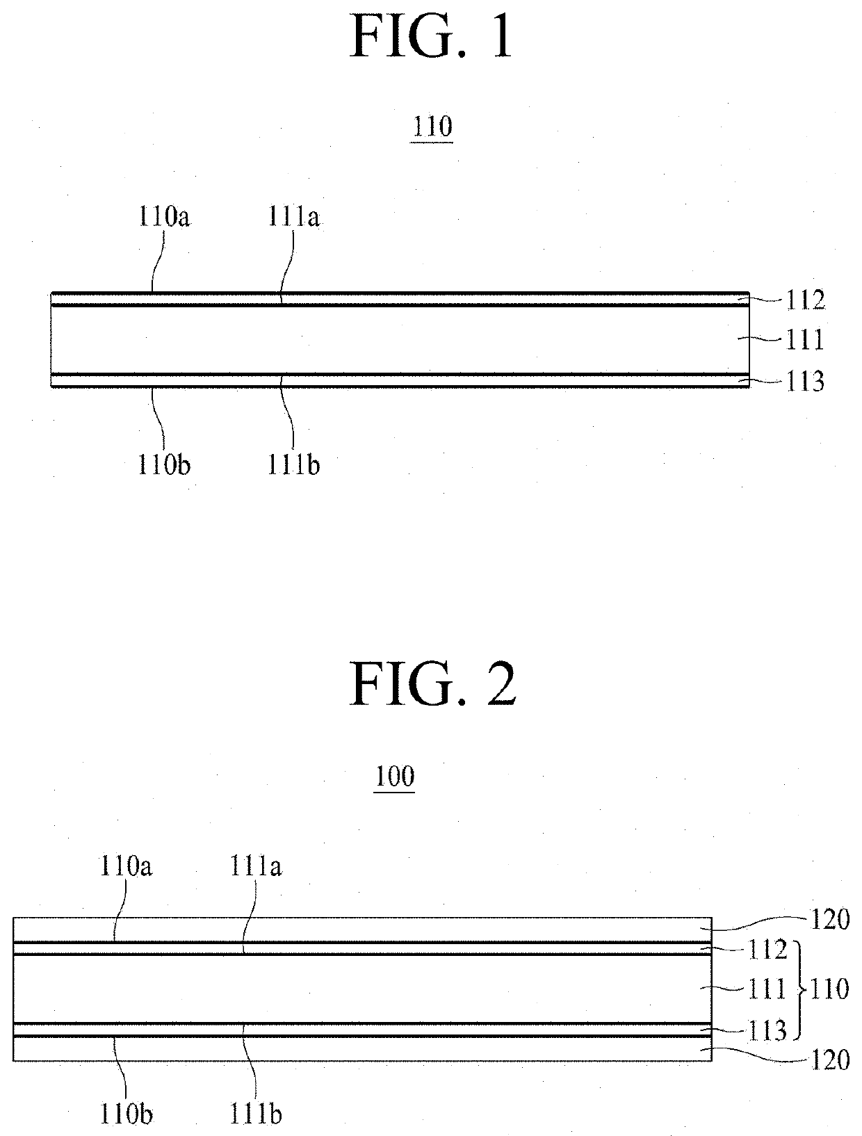
The present invention relates to an electrolytic copper foil current collector where the surface properties are controlled to achieve a high adhesiveness to a negative electrode material. An electrolytic copper foil has a first surface and the second surface, the electrolytic copper foil comprising a first protective layer on the first surface side, a second protective layer on the second surface side, and a copper film between the first and second protective layers, wherein the coupling coefficient at the first surface or second surface of the electrolytic copper foil is 1.5 to 9.4 as represented by coupling coefficient=Rp / μm+peak density / 30+amount of Cr adhesion / (mg / m2) (here, peak density is measured according to ASME standard B46.1). The electrolytic copper foil has a high adhesiveness to a negative electrode material and a low electrical resistance can be provided by controlling the surface properties of the electrolytic copper foil surface.

Description

TECHNICAL FIELD[0001]The present disclosure relates to a copper foil current collector, and more particularly to an electrolytic copper foil that has high force of adhesion with a negative electrode active material of an Li secondary battery.BACKGROUND ART[0002]With an increase in use of portable electronic devices, such as mobile phones and laptop computers, and the population of hybrid vehicles, the demand for Li batteries has abruptly increased.[0003]For a lithium secondary battery, a negative electrode current collector is mainly made of an electrolytic copper foil. The electrolytic copper foil is manufactured through a foil making process using an electroplating method, wherein a shiny surface, which has relatively low roughness, is formed on one surface of the manufactured electrolytic copper foil and a matte surface, which has relatively high roughness, is formed on the other surface thereof. The matte surface of the electrolytic copper foil is coated with an active material,...

Claims


Application Information

Patent Timeline
Patent Type & Authority Applications(United States)
IPC IPC(8): C25D1/04C25D3/38H01M4/70H01M4/66C25D5/48
CPCH01M4/70H01M4/02H01M4/661C25D5/48H01M4/667H01M2004/027C25D3/38C25D1/04Y02E60/10C23C22/27C25D9/08H01M4/13H01M10/052
Inventor KIM, SEUNG MINKIM, HO GUN
Owner SK NEXILIS CO LTD
Learn More