
Method for estimating junction temperature on-line on IGBT power module

a technology of power modules and junction temperature, applied in the field of power electronics and electronic information science, can solve the problems of high failure rate of thermocouples, inability to compensate for degradation of thermal paths, and difficult maintenance, so as to improve measurement accuracy, reduce noise, and simulate better

Active Publication Date: 2020-07-30
WUHAN UNIV
View PDF1 Cites 24 Cited by
  • Summary
  • Abstract
  • Description
  • Claims
  • Application Information

AI Technical Summary

Benefits of technology

The present invention provides a method for estimating the junction temperature of an IGBT power module using a full-bridge inverter and the conduction voltage drop as the temperature-sensitive electrical parameter. The method utilizes the self-heating of the IGBT and the coupling heat of the diode to develop a thermal model and a predictive-corrective rewinding loop to reduce noise and eliminate intermittent effects. The method can be easily integrated into existing power converter control elements and can form a part of a real-time health management or active control system for a power converter.

Problems solved by technology

There are many types of IGBT power module failure modes, and temperature is the main factor causing its failure.
It calculates the junction temperature based on the method of a fixed thermal model, but cannot compensate for degradation of thermal path caused by the influence of aging and cooling conditions.
However, the measurement error and the change of the operation conditions affect the estimated value, and failure rate of the thermocouple is high and the maintenance is difficult.

Method used


Image

  • Method for estimating junction temperature on-line on IGBT power module
  • Method for estimating junction temperature on-line on IGBT power module
  • Method for estimating junction temperature on-line on IGBT power module

Examples


Embodiment Construction

[0057]The present invention will be further described below with reference to specific embodiments and the accompanying drawings.

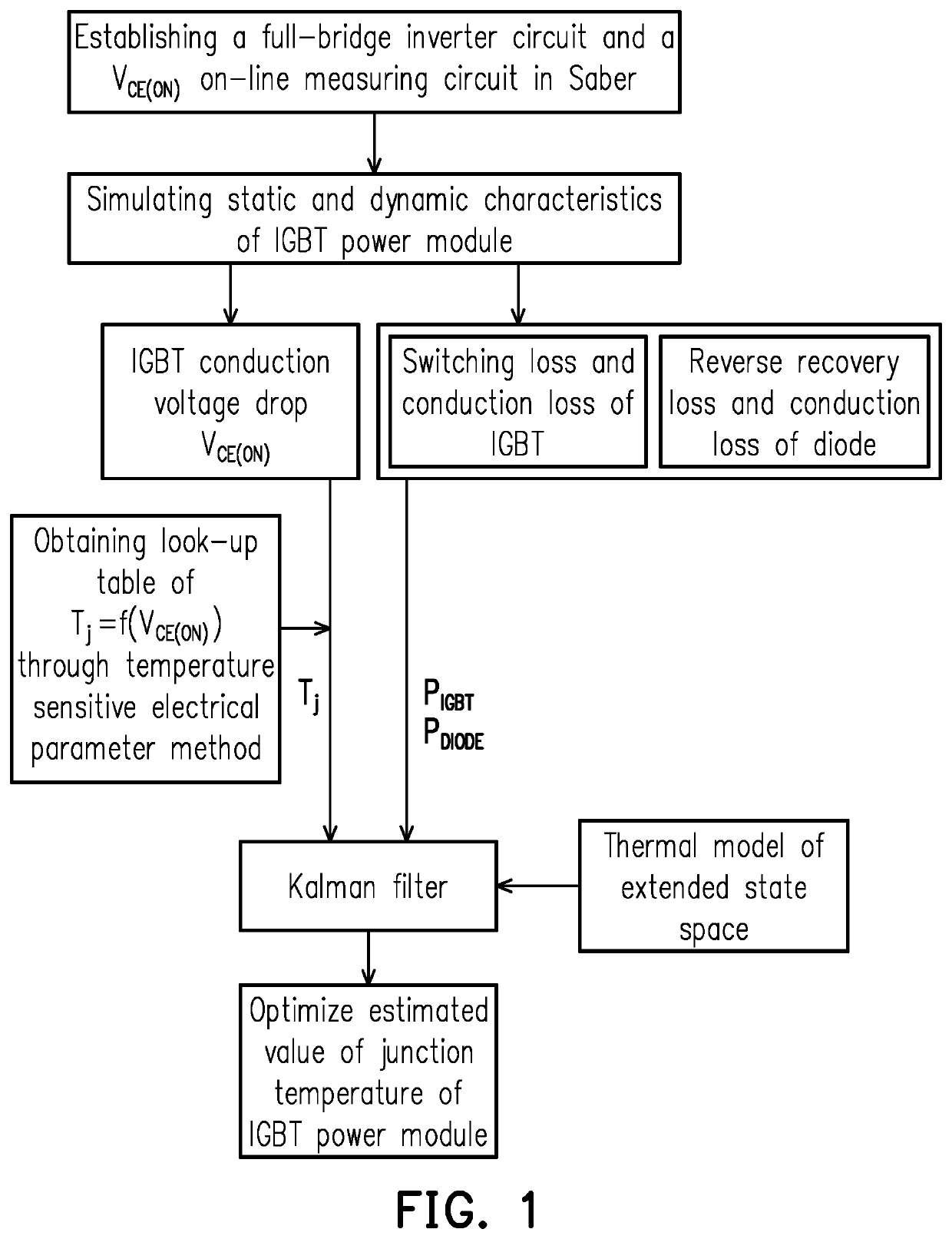
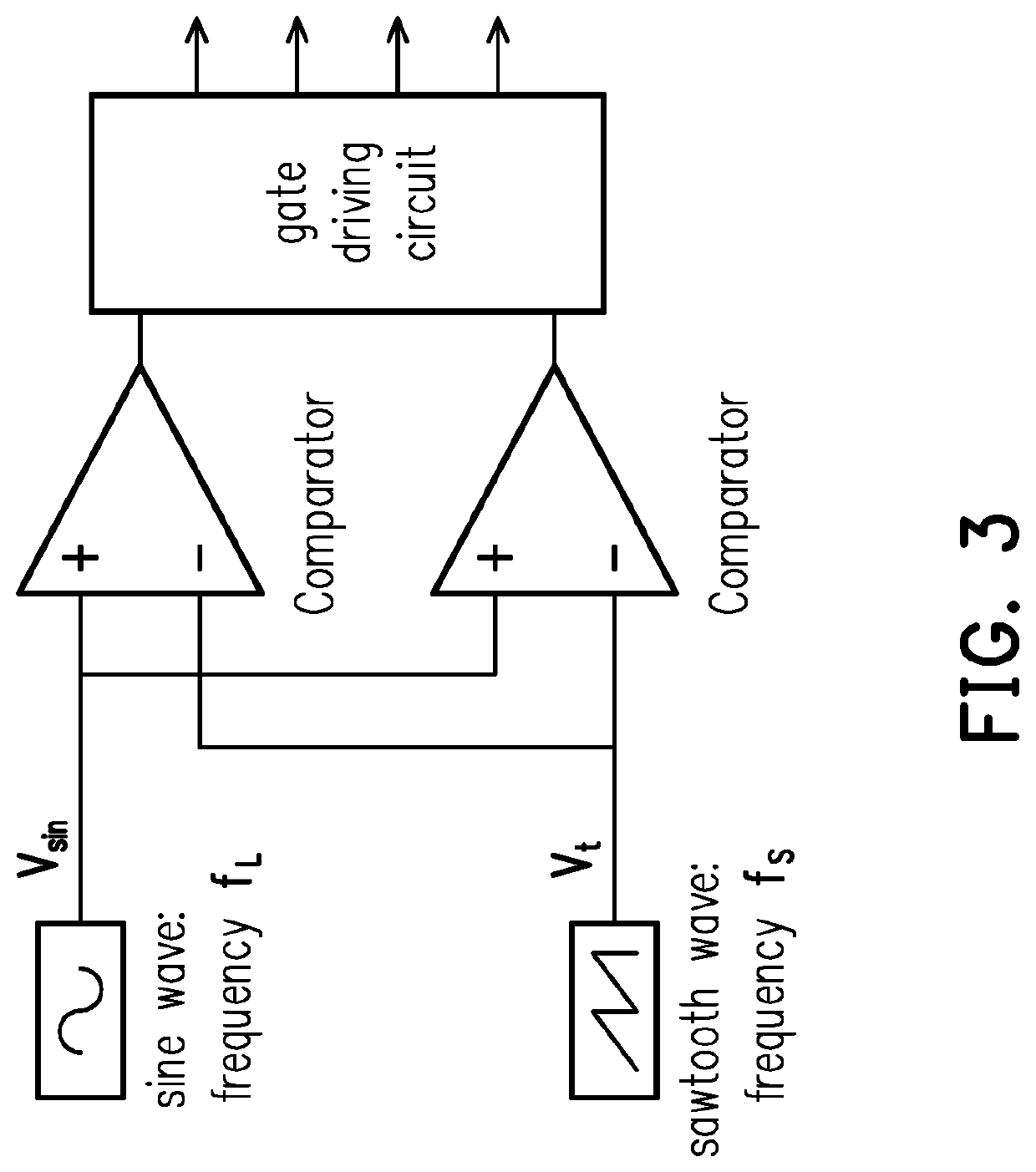
[0058]As shown in FIG. 1, the present invention provides a method for estimating the junction temperature on-line on an IGBT power module. The implementation process of the method is described in detail below by taking the full-bridge inverter circuit shown in FIG. 3 as an example. The specific implementation steps are as follows:

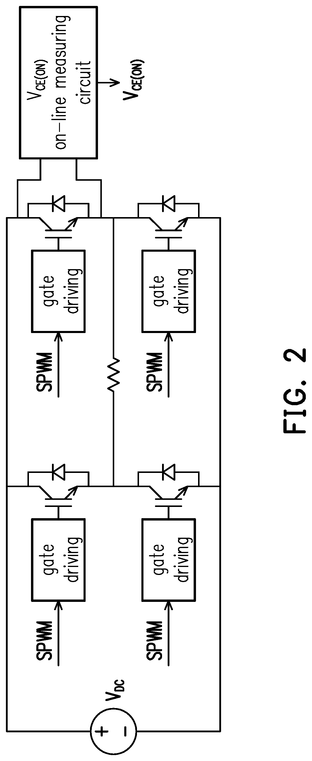
[0059]Step 1. Set up a full-bridge inverter circuit, a VCE(ON) on-line measuring circuit, a SPWM control circuit and a gate driving circuit in Saber, and connect the two input terminals of the VCE(ON) on-line measuring circuit to the collector and emitter of an IGBT of the full-bridge inverter, thereby implementing the connection of the full-bridge inverter circuit to the VCE(ON) on-line measuring circuit, as shown in FIG. 2.

[0060]Specifically, step 1 in the embodiment includes the following process:

[0061]1-1. Referring to the sch...


PUM


Abstract

A method for estimating the junction temperature on-line on an insulated gate bipolar transistor (IGBT) power module, including the following steps. Estimate the junction temperature by the temperature sensitive electrical parameter method, set the space thermal model of the extended state, and apply the Kalman filter to the junction temperature estimation. The temperature sensitive electrical parameter method estimates the junction temperature of the IGBT power module in real time, selects the IGBT conduction voltage drop VCE(ON) as the temperature sensitive electrical parameter, and provides a VCE(ON) on-line measuring circuit. The power loss of the diode and IGBT and the estimated value of junction temperature obtained by the temperature sensitive electrical parameter method are taken as the input of the Kalman filter, and measurement noise and process noise are considered to obtain an optimal estimated value of junction temperature.

Description

CROSS-REFERENCE TO RELATED APPLICATION[0001]This application claims the priority benefit of China application serial no. 201910069446.2, filed on Jan. 24, 2019. The entirety of the above-mentioned patent application is hereby incorporated by reference herein and made a part of this specification.BACKGROUNDTechnical Field[0002]The invention belongs to the field of power electronics and electronic information science, and particularly relates to a method for estimating the junction temperature on-line on an IGBT power module, and uses the Kalman filter to obtain an optimal estimation value of the junction temperature.Description of Related Art[0003]Power converters are widely used in the fields related to smart grids, rail transit and new energy sources. Insulated gate bipolar transistors (IGBT) are the key components of power converter devices, and their reliability is the guarantee for safe operation of the system. Therefore, monitoring the condition and predicting the service life ...

Claims


Application Information

Patent Timeline
IPC IPC(8): G01K13/00G01K7/01
CPCG01K7/015G01K13/00G01K7/01G01K7/42G01K2217/00G06F17/10G06F17/15
Inventor HE, YIGANGLI, KAIWEIYUAN, WEIBOHE, LIULUGUO, YUZHENGZHANG, HUI
Owner WUHAN UNIV
Learn More