
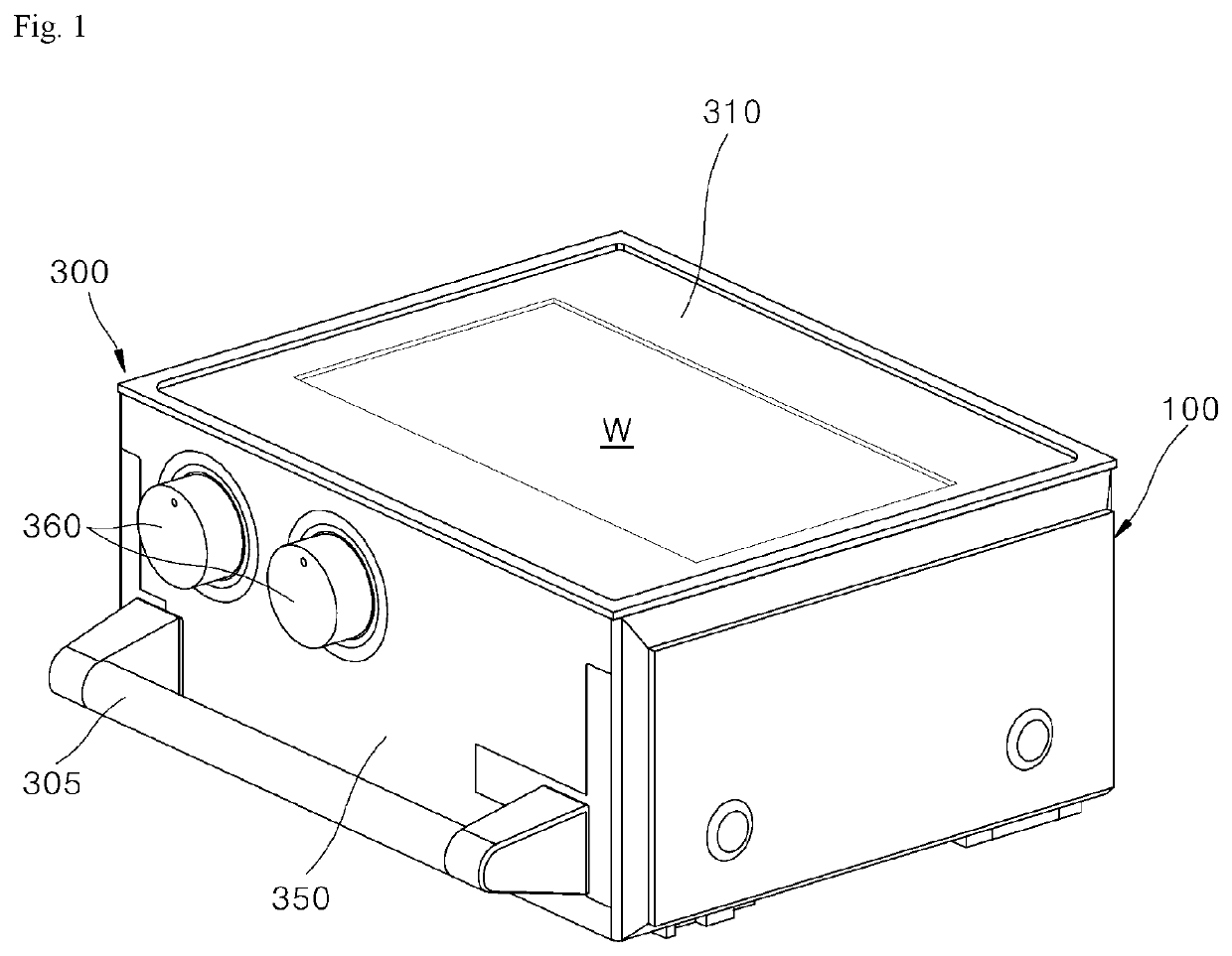
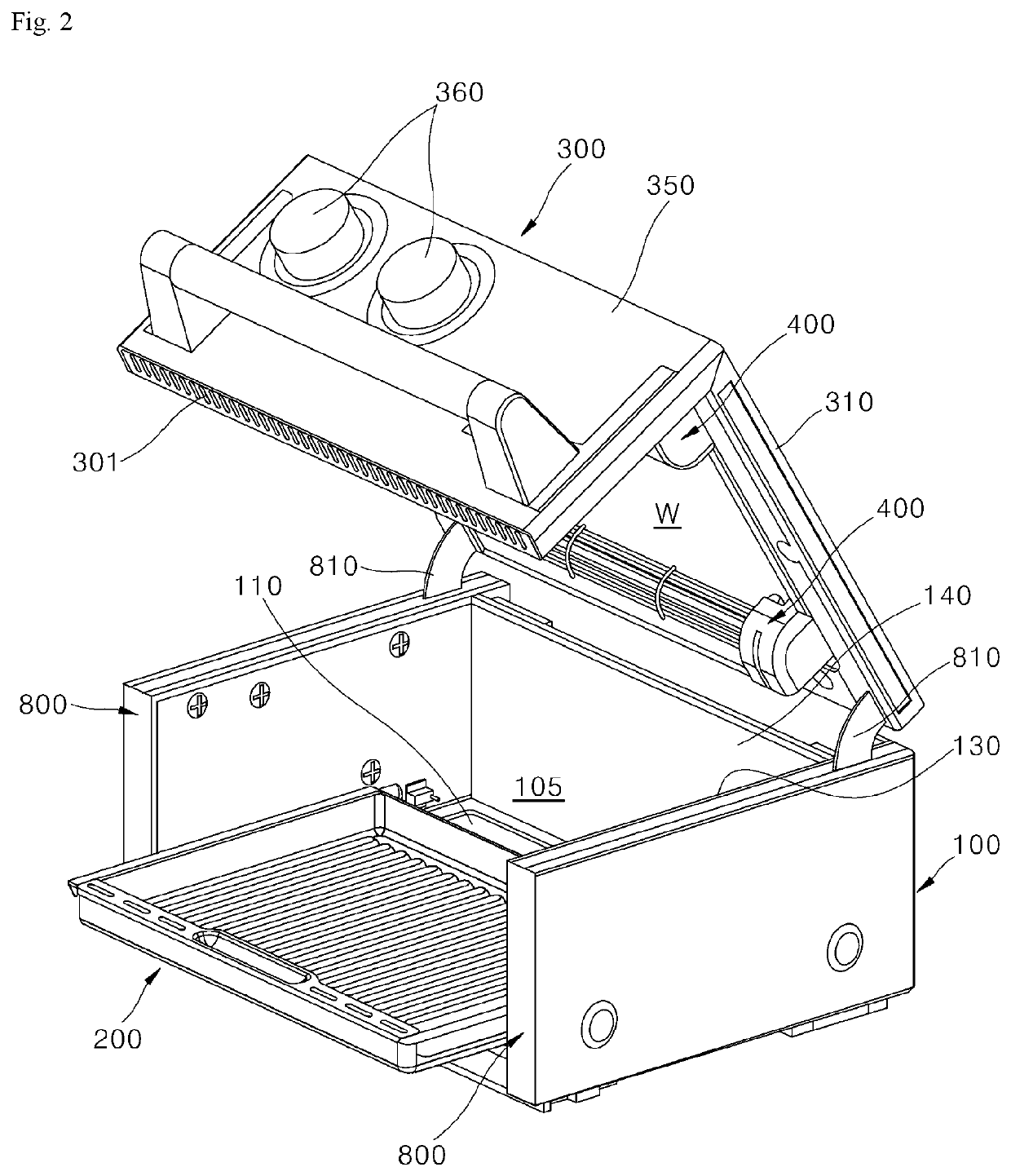
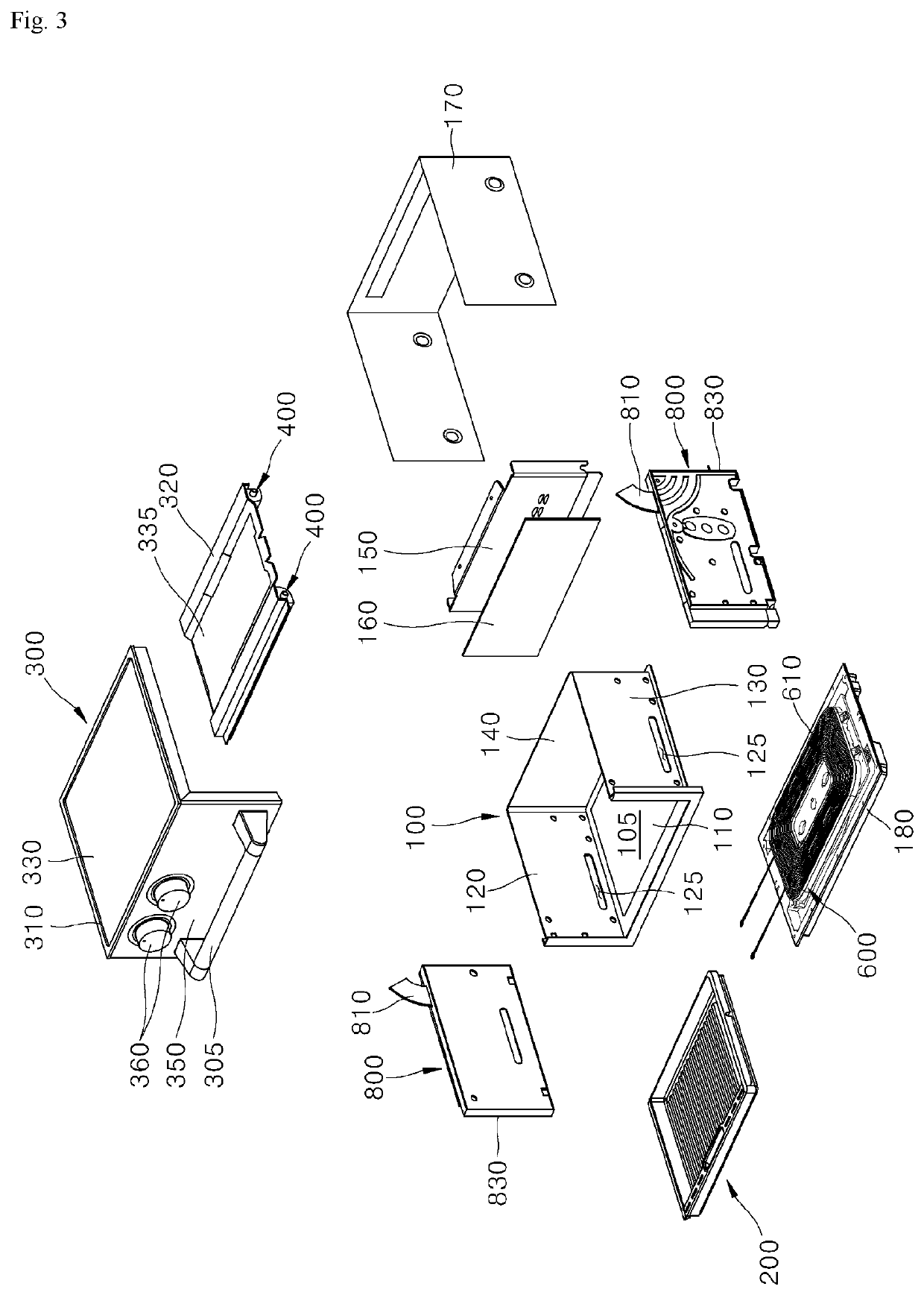
Cooking applicance

a technology for cooking appliances and cooking surfaces, applied in the field of cooking appliances, can solve the problems of unexpected inconvenience in changing the installation position of the mini oven as needed, reducing the advantages of the mini oven described above, and reducing the size of the mini oven. , to achieve the effect of small cooking appliances, easy change of position, and preventing the increase of the size of the cooking appliances

Active Publication Date: 2020-07-16
LG ELECTRONICS INC
View PDF0 Cites 6 Cited by
  • Summary
  • Abstract
  • Description
  • Claims
  • Application Information

AI Technical Summary

Benefits of technology

The cooking appliance described in this patent is designed to be easily cooled even when installed in a narrow space. It allows for compact placement of components that can smoothly cool while still maintaining efficient heating and wireless power supply. This is achieved by effectively managing the heat generated during the cooking process, resulting in improved performance.

Problems solved by technology

The mini ovens have a small size and are thus not suitable for cooking food of a large size but are suitable for baking or warming a small amount of food which does not require the use of large-capacity ovens.
However, since a power cable for supplying power is connected, it is unexpectedly inconvenient to change an installed position of the mini oven as needed.
However, according to this solution, since components required to wirelessly receive power increase a volume and weight of the mini oven, the advantages of the mini oven described above may be reduced by half.
Further, since the cooking appliance converts electricity into heat, power consumption thereof is high.
Therefore, the cooling appliance needs to be wirelessly supplied with a large quantity of power.
However, this causes a problem in that the volume and weight of the mini oven are increased.
Further, if a coil is disposed to reduce the volume, the coil is not easily cooled, which leads to a problem in that efficiency of the coil is lowered.
Thus, heating efficiency and wireless power supply efficiency are not reduced due to heat generated in the process of actuating the cooking appliance.

Method used


Image

  • Cooking applicance
  • Cooking applicance
  • Cooking applicance

Examples


Embodiment Construction

[0113]The above-mentioned objectives, features, and advantages will be described in detail with reference to the accompanying drawings, and accordingly, those of ordinary skill in the art to which the present disclosure pertains should be able to easily practice the technical idea of the present disclosure. In describing the present disclosure, when detailed description of known art related to the present disclosure is deemed as having a possibility of unnecessarily blurring the gist of the present disclosure, the detailed description will be omitted. Hereinafter, exemplary embodiments according to the present disclosure will be described in detail with reference to the accompanying drawings. Like reference numerals in the drawings refer to like or similar elements throughout.

[0114]Terms such as first and second are used to describe various elements, but the elements are of course not limited by the terms. The terms are merely used for distinguishing one element from another element...


PUM


Abstract

Disclosed herein is a cooking appliance. A working coil is provided at a lower portion of the cooking appliance. The working coil heats a tray disposed in a cooking compartment in an IH mode. A receiver coil wirelessly receiving external power is stacked below the working coil. An electromagnetic shielding plate is installed between the working coil and the receiver coil to partition a space in which the two coils are installed. The electromagnetic shielding plate shields an electromagnetic field or electromagnetic waves such that the electromagnetic field or electromagnetic waves in one of the two partitioned spaces does not leak to the other space located across the electromagnetic shielding plate.

Description

CROSS-REFERENCE TO RELATED APPLICATION[0001]This application claims priority to and the benefit of Korean Patent Application No. 10-2019-0004169 filed on Jan. 11, 2019, Korean Patent Application No. 10-2019-0040378 filed on Apr. 5, 2019, and Korean Patent Application No. 10-2019-0082347 filed on Jul. 8, 2019, the disclosure of which are incorporated herein by reference in their entirety.BACKGROUND1. Technical Field[0002]The present disclosure relates to a cooking appliance, and more particularly, to a cooking appliance, such as an oven, including a door for opening and closing a cooking compartment.2. Related Art[0003]Cooking appliances, which are one kind of home appliances that are used for cooking food, are appliances installed in a kitchen space for cooking food according to a user's intention. Cooking appliances may be classified in various ways according to heat sources or forms used therein or types of fuels used therein.[0004]When classified according to the form of cooking ...

Claims


Application Information

Patent Timeline
Patent Type & Authority Applications(United States)
IPC IPC(8): H05B6/12H05B6/06F24C7/08
CPCH05B6/1245H05B6/062H05B2213/03H05B2206/02F24C7/08H05B6/129A47J37/0629H02J50/10H02J50/005
Inventor KIM, HAG SOOKIM, EUI SUNGYOON, SUNG MUN
Owner LG ELECTRONICS INC
Learn More