Method for Bone Scan in Meat

a bone scan and meat technology, applied in the field of bone scan in meat, can solve the problems of biomolecules present, bone fragments pose both a regulatory risk and a litigation risk to food processing operations, and human health risks, and achieve the effects of preventing abrasion, minimizing or eliminating specular reflectance, and high probability of presen

Active Publication Date: 2020-07-09
7386819 MANITOBA LTD
View PDF0 Cites 1 Cited by
  • Summary
  • Abstract
  • Description
  • Claims
  • Application Information

AI Technical Summary

Benefits of technology

[0039]The principal object is to provide a robust and economical means to detect small defects both on the surface and deep within the bulk of meat.
[0072]All optical measurements are made in approximate backscatter geometry to eliminate possible shadowing effects due to irregular sample shapes. The illumination is diffuse to limit the effect of specular reflection and as homogeneous as possible. Diffuse illumination is achieved by using an extended source composed of one or more Lambertian radiators. A diffuser plate may be used to improve homogeneity. The illumination may optionally be polarized, with a polarizer rotated 90° with respect to the incident polarization positioned between the sample and detector to reduce specular reflection. The general direction of illumination is more than 150°, preferably as close to 180° as possible, allowing for spatial considerations, usually within 5°. It can be 180° if a beam splitter is used. The space between the illumination and sample may be air, but is more preferably a liquid to reduce changes in the refractive index. In another embodiment, a roller comprised of a material that transmits in the wavelength region of interest is placed in contact with the sample. The roller is cleaned to prevent the buildup of a biofilm. In all embodiments, an optical system composed of reflective and / or refractive elements is used to map radiation scattered or reflected from a small surface region of the sample with magnification onto a detector element. The linear dimensions of the small surface region are x / 2 and the corresponding spatial frequency is 2 / x. The Nyquist Theorem requires sampling at 2 / x to resolve features with spatial frequency 1 / x. Further, the optical system must transfer modulations of spectral frequency 2 / x with high fidelity as determined by analysis of the modulation transfer function. The optical detector element is a photodiode, or a bolometer. A bolometer, which responds to electromagnetic radiation over a wide range of wavelengths, is less sensitive and has a slower response time. A bolometer is sensitive to air currents and is usually encased in a vacuum enclosure with an optical window. The optical characteristics of the window material determine the practical wavelength range of the bolometer.
[0078]In another embodiment, a laser provides quasi-monochromatic illumination and Raman scattered radiation is dispersed by wavelength and position on a focal plane array, the laser provides better spectral resolution.
[0087]Preferably the optical system is enclosed in a chamber shielded from ambient light, including the effect of 60 Hz fluorescent lighting. Modulating the amplitude of illumination and passing the modulation signal to a lock-in amplifier linked with the detector outputs can eliminate the effect of ambient light.Acoustic Measurements
[0100]The products to be inspected may be in air. In this instance, a disposable transparent film separates the optics from the sample area. The film may be slowly scrolled between two rollers at a rate that maintains a clear field of view between the sample and detector. It is understood that an optical inspection apparatus can be positioned to face each surface of the sample. In a preferred embodiment, one set of optical detectors faces the top surface of a sample and a second set of optical detectors faces the bottom surface. Preferably, the sample is immersed in a clear liquid solution, which minimizes or eliminates specular reflectance, during optical scanning and also couples acoustic waves into the sample more effectively than an air interface. The clear liquid solution may be primarily water. In this embodiment, a submerged clear window separates the optics from the sample. The clear window is preferably recessed to prevent abrasion and cleaned periodically to prevent the accumulation of a biofilm.

Problems solved by technology

Bone fragments or hard objects larger than 1 mm in size, which may be present in food products, pose a risk to human health.
Consequently bone fragments pose both a regulatory risk and a litigation risk to food processing operations.
Other biomolecules are present, but not in sufficient quantity to have a significant effect on the types of measurements discussed herein.
The technical problem is to find bone in a meat matrix composed of protein and lipid.
The primary weakness of this method is that tissue scatters photons at every refractive index discontinuity, effectively on the scale of cellular dimensions.
The candling method is thus limited to thin samples with uniform thickness.
Secondly, the signal from a small defect can be lost within a larger signal from texture within the meat matrix.
The UV fluorescence method, like the candling method is limited to thin samples due to the high photon scattering cross section of flesh.
The x-ray method has limited capability to detect weakly mineralized bones and cartilage or account for variation in sample thickness.
U.S. Pat. No. 7,060,981 CT increased speed by using multiple sources at increased cost
Several problems remain, even with the most recent CT systems.
X-ray emitters use high voltage and are operated in a damp environment posing further risk to workers.
The high capital cost and high cost of maintenance have limited the adoption of x-ray methods in food processing applications.

Method used


Image

  • Method for Bone Scan in Meat
  • Method for Bone Scan in Meat
  • Method for Bone Scan in Meat

Examples


Embodiment Construction

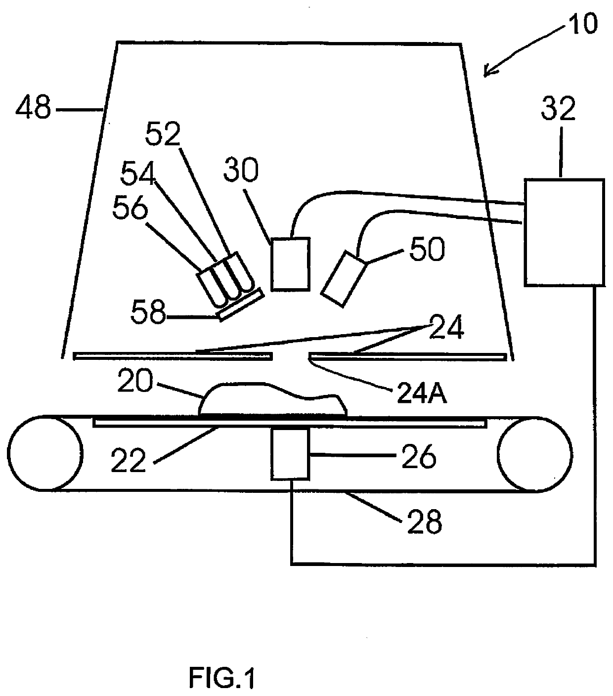
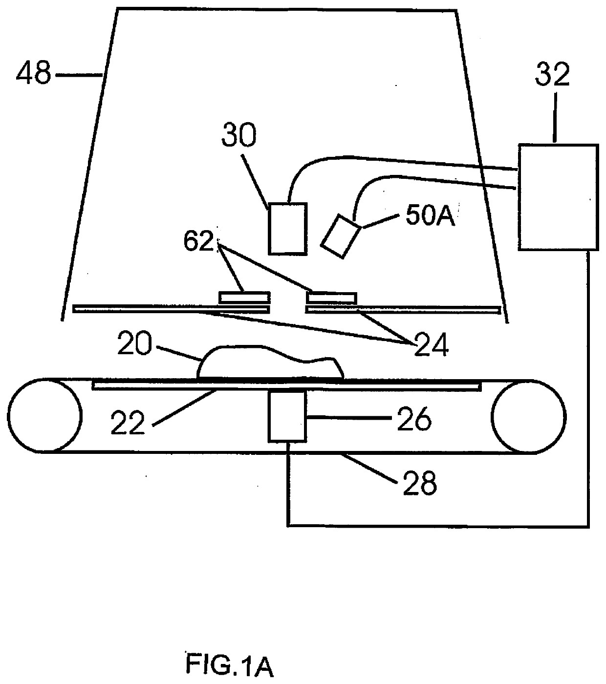
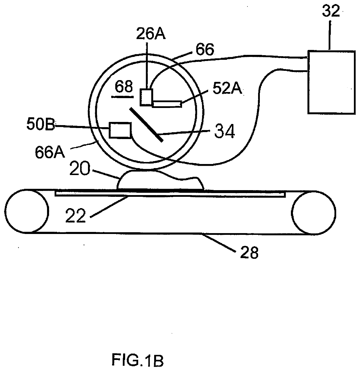
[0071]The arrangement described herein provides methods for the detection of foreign material on the surface or in the bulk of food products with a combination of spectral imaging and ultrasound measurements. Very loosely spectral imaging is used to detect foreign material proximate to the surface and ultrasound is used to detect foreign material within the sample bulk. The sample is irradiated by light and reflected light or Raman scattered light measured to give a set of amplitude data points. The sample is similarly irradiated by ultrasound and reflected sound waves give a set of amplitude data points, which include temporal delay. These spectral and acoustic data points are then processed by statistical methods to derive a set of vectors in n-dimensional space. These vectors are indicative of the presence or absence of defects. Typically the vectors indicate the presence of bone, cartilage, fat, flesh (meat or muscle in the narrow sense), or skin in the sample, and thus the pres...


PUM

PropertyMeasurementUnit
wavelength rangeaaaaaaaaaa

Abstract

A method and device for detection of bone in meat identifies fragments larger than about 1 mm using spectral optical imaging and ultrasound. Spectral imaging can detect foreign material proximate to the surface and ultrasound can detect material within the sample. The sample is irradiated by light and reflected light or Raman scattered light measured. The sample is similarly irradiated by ultrasound and reflected or transmitted sound waves give a set of amplitude data points, which include temporal delay. These data points are then processed by statistical methods to derive a set of vectors in n-dimensional space, which are compared to a calibrated data set of derived vectors which have distinct identifying loci for each type of surface, are indicative of the presence or absence of defects.

Description

[0001]This application is a continuation of application Ser. No. 15 / 327,715 which is a 371 of PCT / CA2015 / 050678 filed Jul. 21 2015 and claims benefit under 35 USC 119(e) from Provisional application 61 / 999,206 filed Jul. 21 2014.[0002]The present invention pertains to the detection of small objects wholly or partly embedded in soft tissue. Generally, although not essentially, the objects are bone fragments or very small bones in meat. Large bones are not a problem because they are easily visible. Commercially, most typically, the meat is chicken breast, as the bone tends to fragment when the breast is deboned. The invention can also be applied to poultry, fish, and other meats liable to contain bone fragments or very small bones.BACKGROUND OF THE INVENTION[0003]Bone fragments or hard objects larger than 1 mm in size, which may be present in food products, pose a risk to human health. Consequently bone fragments pose both a regulatory risk and a litigation risk to food processing ope...

Claims


Application Information

Patent Timeline
Patent Type & Authority Applications(United States)
IPC IPC(8): G01N33/12G01N21/3563G01N21/65A22C17/00G01N21/94G01N29/07
CPCA22C17/0073G01S7/52036G01N2021/3595G01N29/07G01N2201/129G01S15/88G01N21/94G01N33/12G01N21/3563G01N21/65
Inventor PRYSTUPA, DAVID
Owner 7386819 MANITOBA LTD
Why Eureka
Try Eureka