Melting apparatus for the production of steel

Active Publication Date: 2020-05-28
DANIELI & C OFF MEC SPA
View PDF0 Cites 1 Cited by
  • Summary
  • Abstract
  • Description
  • Claims
  • Application Information

AI Technical Summary

Benefits of technology

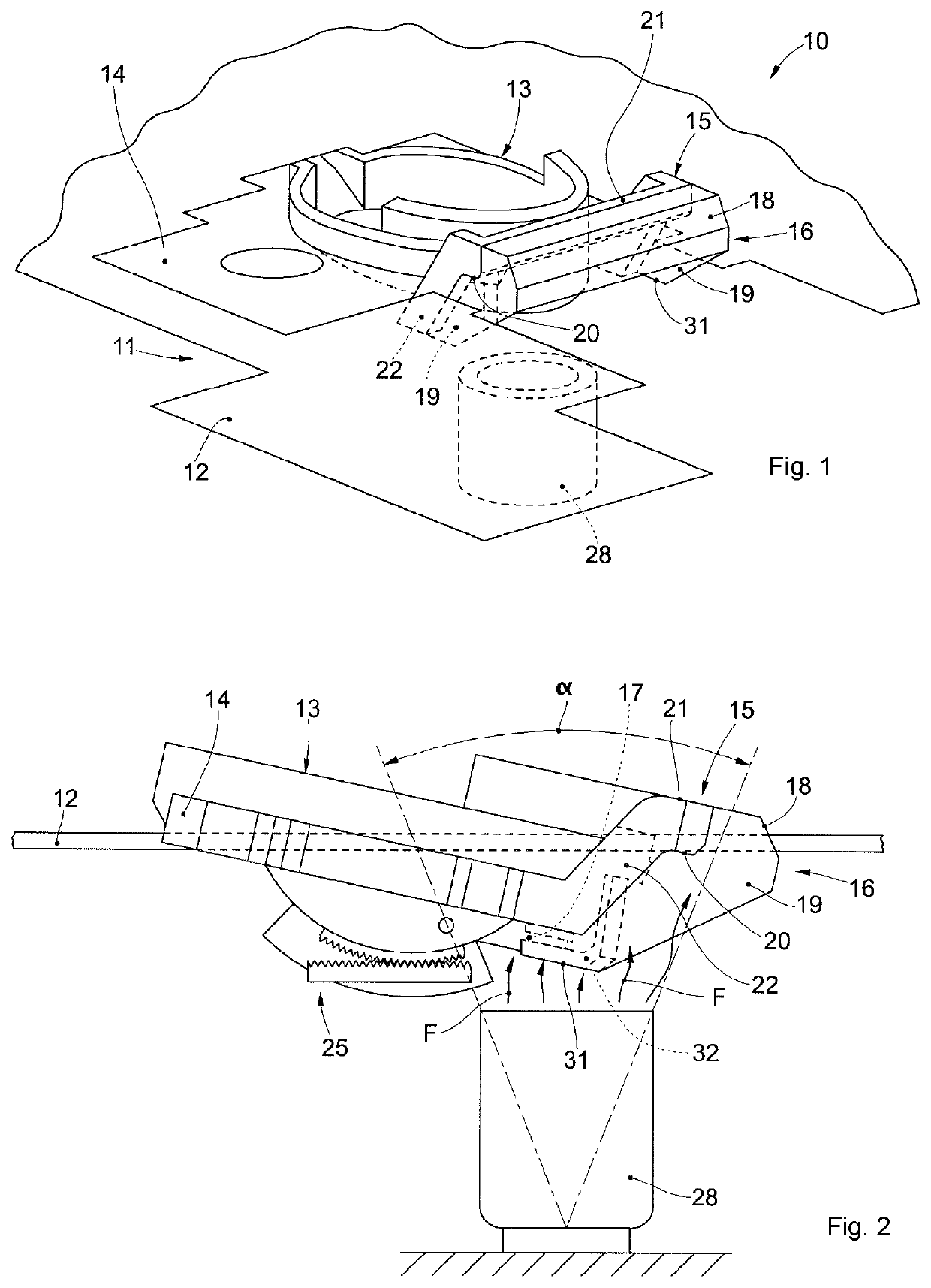
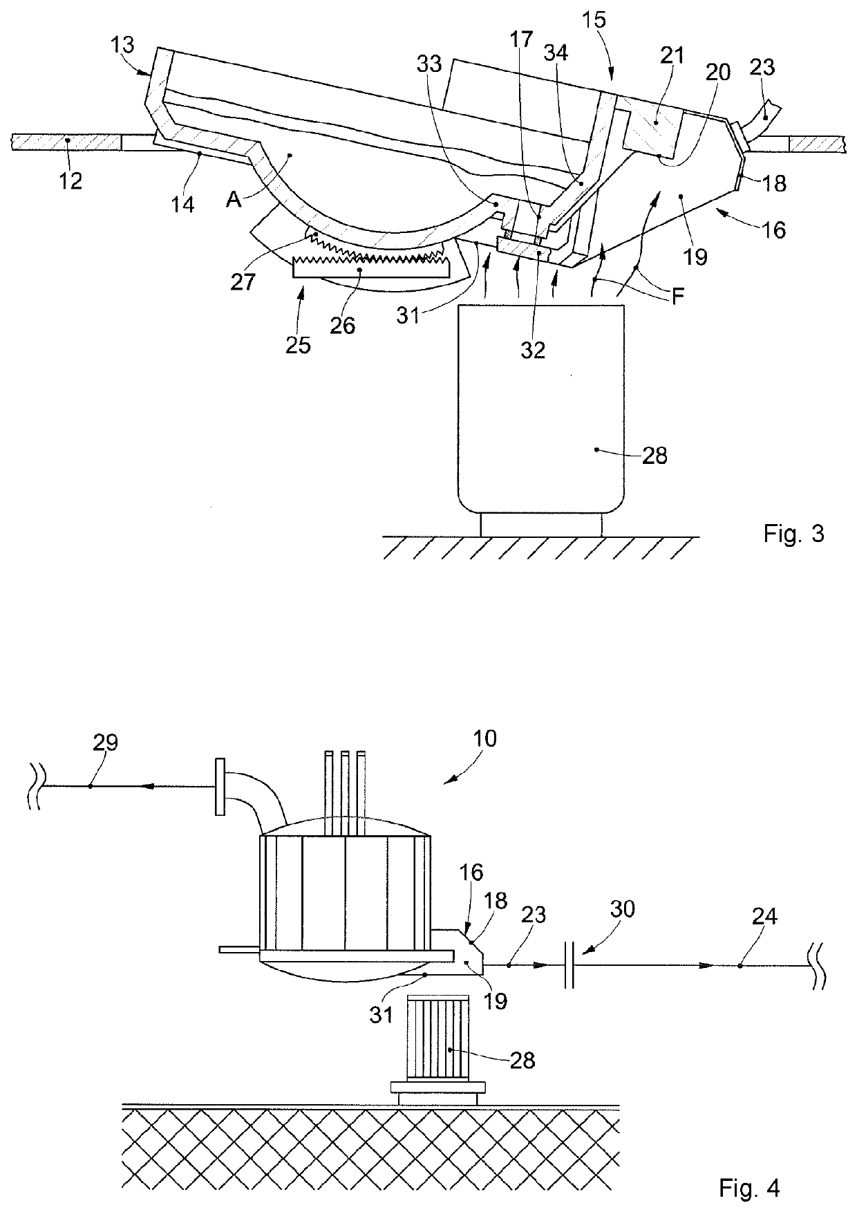
The melting apparatus has a fume emission zone at the bottom of the shell. An E.B.T. is placed directly above this zone, which reduces the contact between liquid steel and air. This eliminates the need for another spout or tubular tapping element.

Problems solved by technology

The use of the main hood proves to be quite effective if the hood is compartmentalized inside, however the use of the main hood can present several disadvantages in the event of possible external actions, such as the presence of air currents inside the building where the melting apparatus is housed, which can be generated, for example, by heat sources, the movement of machines, the movement of materials, or other.
Localized tapping hoods are instead positioned in proximity to the melting apparatus, but laterally to the tapping zone or to the zone where the fumes are emitted, therefore they do not guarantee an effective and complete suction of the fumes coming from the aperture through which the steel exits from the shell, nor do they guarantee the correct capture of the fumes that rise from the ladle where the tapped steel is poured.
Other problems of known suction systems also concern the convergence of the suction line from the main hood of the furnace with the suction line of the fumes coming from the tapping zone, and therefore the delivery of the fumes to a single conveyor collector, with obvious disadvantages in the management of the emissions both from the main furnace and from the tapping zone.
Other disadvantages of known melting apparatuses are linked to the fact that it is necessary to provide fume treatment plants which generally require high power, entail high energy expenditure and often large bulk, with negative consequences with regard to the costs and overall size of the melting apparatus or plant.
These disadvantages are particularly relevant in melting apparatuses with continuous charging of the furnace, in which, therefore, the sizing of the fume treatment plant is generally calibrated for the tapping step.
Also the melting apparatuses known and described for example in the documents DE-A-3805226, FR-A-3354768 and DE-A-4103122 have the above disadvantages: in particular in the above documents a tapping spout or pipe is used for the passage of the molten steel from the apparatus to a ladle, or suchlike, therefore the liquid steel, during pouring into the ladle, normally remains for a long time and undesirably in contact with the air in an intermediate zone between the melting apparatus and the ladle.

Method used


Image

  • Melting apparatus for the production of steel
  • Melting apparatus for the production of steel

Examples


Embodiment Construction

[0046]We will now refer in detail to the various embodiments of the present invention, of which one or more examples are shown in the attached drawings. Each example is supplied by way of illustration of the invention and shall not be understood as a limitation thereof. For example, the characteristics shown or described insomuch as they are part of one embodiment can be adopted on, or in association with, other embodiments to produce another embodiment. It is understood that the present invention shall include all such modifications and variants.

[0047]Before describing the embodiments, we must also clarify that the present description is not limited in its application to details of the construction and disposition of the components as described in the following description using the attached drawings. The present description can provide other embodiments and can be obtained or executed in various other ways. We must also clarify that the phraseology and terminology used here is for...


PUM

PropertyMeasurementUnit
Shapeaaaaaaaaaa
Levelaaaaaaaaaa

Abstract

A melting apparatus for steel production includes a support structure to support a shell for the production and tapping of steel, and a source or zone for the emission of fumes resulting from the tapping of the steel from the shell. The melting apparatus also includes a tapping hood integrated into the support structure and provided with a suction mouth positioned directly above the zone for the emission of fumes, the shell is provided with a bottom wall in which an E.B.T. is provided for tapping the steel.

Description

FIELD OF THE INVENTION[0001]The present invention concerns a melting apparatus for the production of steel, for example an electric arc furnace provided with at least one fume tapping hood located in a zone of the melting apparatus dedicated to the tapping of the steel.BACKGROUND OF THE INVENTION[0002]As is known, melting apparatuses, such as in particular electric arc furnaces, are generally used in metallurgy for the production of steel, starting, for example, from scrap, DRI (direct reduced iron), briquettes, cast iron, or suchlike.[0003]The electric arc furnaces can be mainly of two types, alternating current or direct current, and can typically provide a spout-type tapping system.[0004]Some known apparatuses for melting and producing steel, in particular electric arc or induction furnaces, are described for example in documents DE-A-3805226, FR-A-3354768 and DE-A-4103122.[0005]In electric arc furnaces it is possible to distinguish substantially three operating steps: the chargi...

Claims


Application Information

Patent Timeline
IPC IPC(8): B22D45/00B08B15/04F27D17/00F27B3/19F27B3/12B08B15/02C21C5/40
CPCF27B3/12C21C2100/00B22D45/005F27B3/19F27D17/003F27D17/002C21C5/40B08B15/02B08B15/04F27D17/001Y02P10/20
Inventor BEVILACQUA, MASSIMOBERTOLISSIO, ARRIGO
Owner DANIELI & C OFF MEC SPA
Why Eureka
Try Eureka