
Additive manufacturing of complex objects using refractory matrix materials

a technology of refractory matrix materials and additive manufacturing, which is applied in the direction of nuclear elements, machines/engines, nuclear engineering, etc., can solve the problems of inability to readily produce components of higher complexity, such as heat exchangers, flanges, turbines,

Active Publication Date: 2020-05-21
UT BATTELLE LLC
View PDF0 Cites 5 Cited by
  • Summary
  • Abstract
  • Description
  • Claims
  • Application Information

AI Technical Summary

Benefits of technology

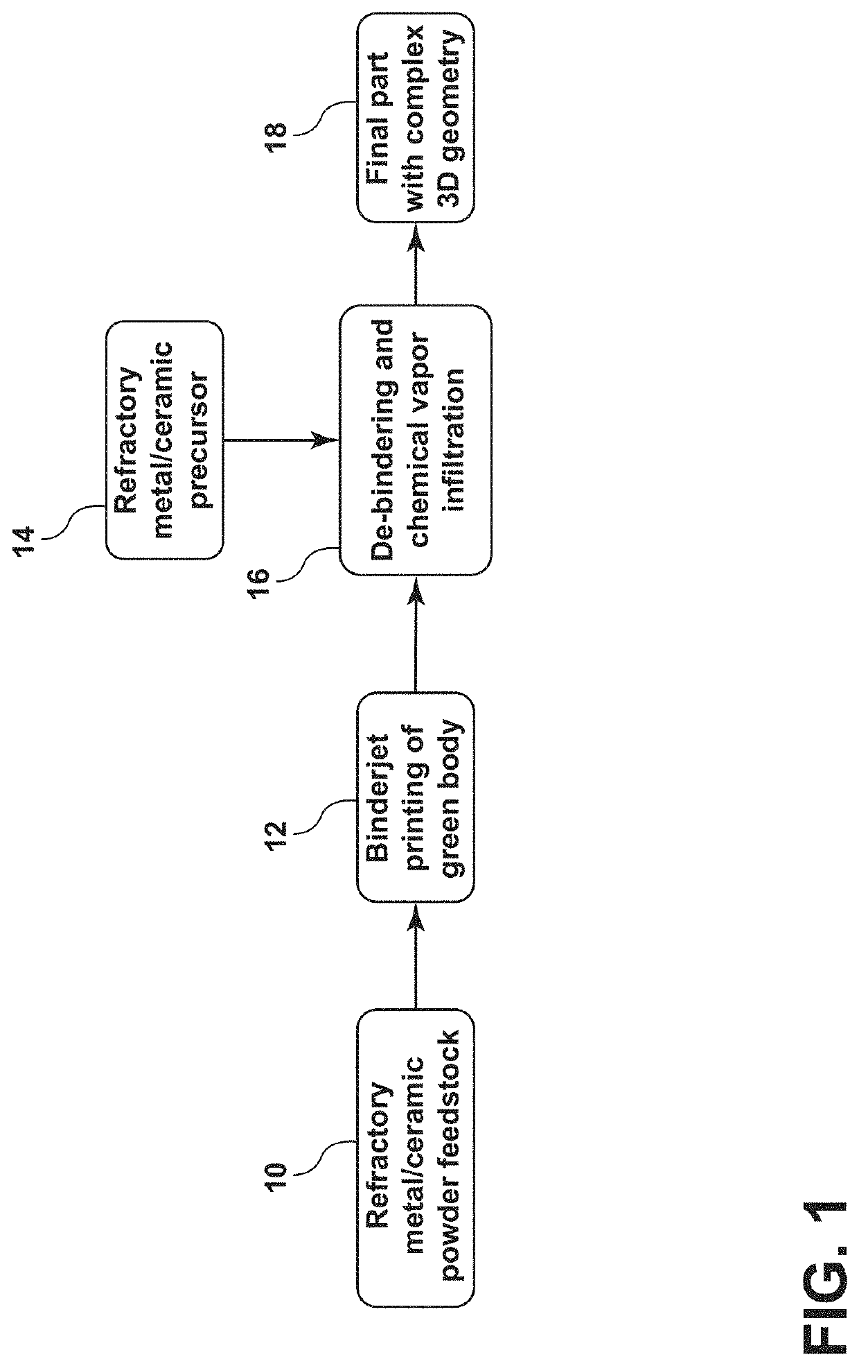
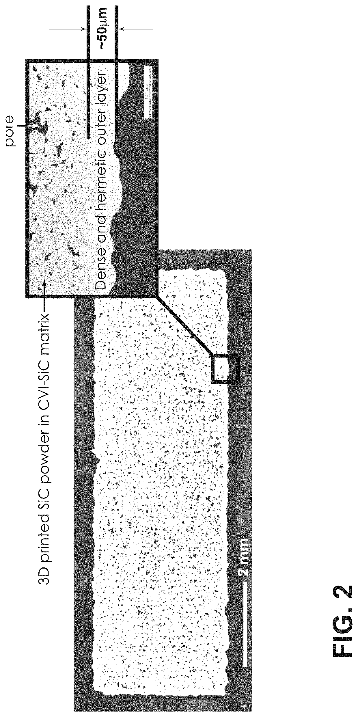
The patent describes a method for making three-dimensional objects using a refractory material. The method involves creating a green body from a powder-based refractory material and then chemically depositing a coating on it using chemical gas infiltration. This process increases the density of the refractory material and results in objects with excellent mechanical integrity at very high temperatures. The method can be used to make objects with complex geometries and is suitable for applications where high heat resistance is needed. The green body is formed at room temperature, and the chemical gas infiltration process operates at temperatures below sintering temperatures. In some embodiments, the packing fraction of nuclear fuel particles is greater than 50%, outpacing the packing density of pressed and sintered nuclear fuels, resulting in smaller nuclear fuel assemblies.

Problems solved by technology

While the production of simple geometries (e.g., piping) from refractory metals or ceramics is possible today, components of higher complexity, for example heat exchangers, flanges, and turbines, are not readily produced.

Method used


Image

  • Additive manufacturing of complex objects using refractory matrix materials
  • Additive manufacturing of complex objects using refractory matrix materials
  • Additive manufacturing of complex objects using refractory matrix materials

Examples


Embodiment Construction

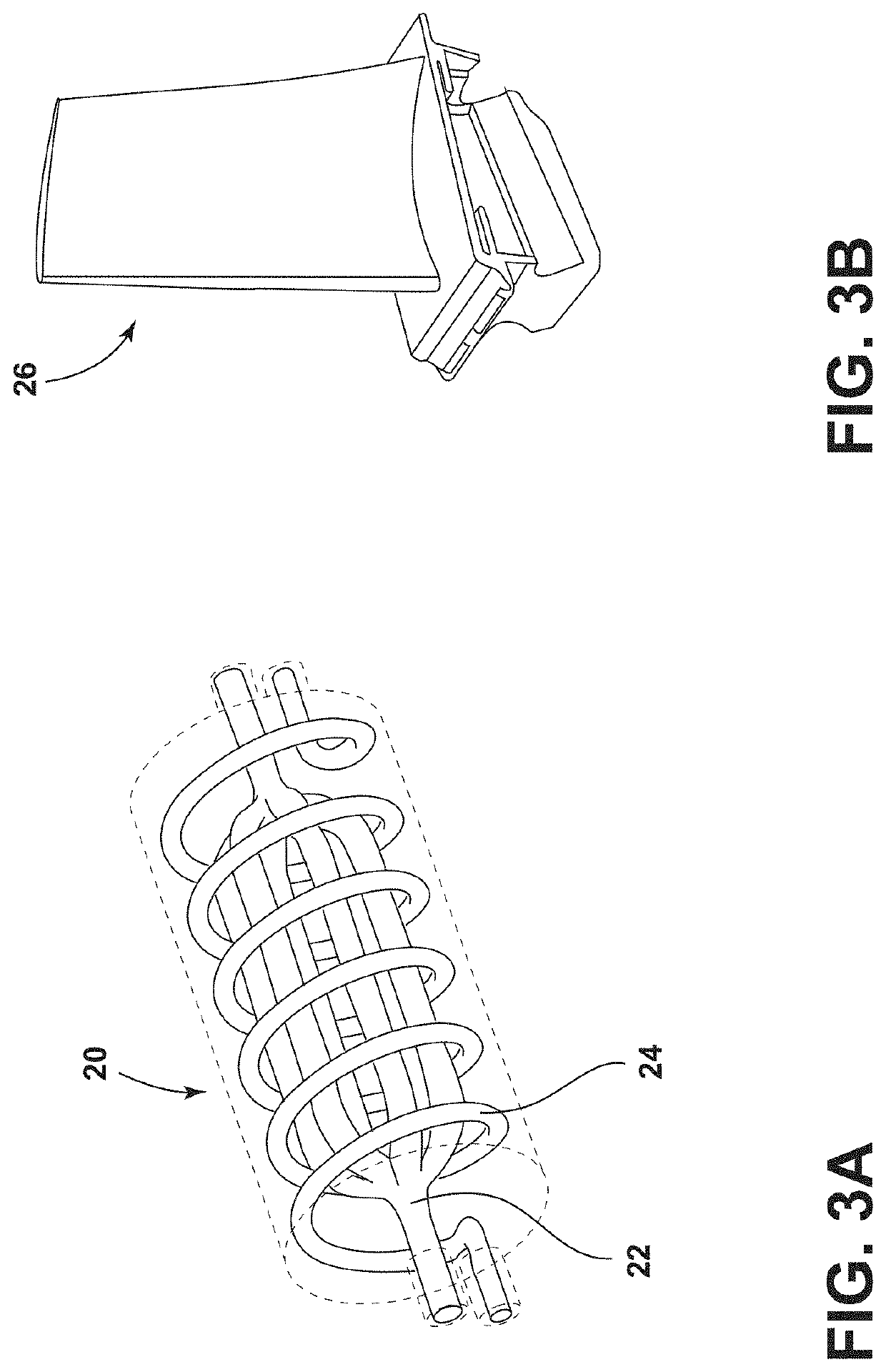
[0022]As discussed herein, the current embodiments generally relate to a method for the manufacture of a wide-variety of object using a refractory matrix material. The method includes the additive manufacture of a green body from a powder-based refractory matrix material followed by densification via CVI. The method of manufacture is generally discussed in Part I below, followed by a description of an integral nuclear fuel element formed according to this method in Part II below. Though described in connection with a nuclear fuel element, the present method is applicable in effectively any application in which a complex three-dimensional object requires high heat resistance, including heat exchangers, flanges, and turbines blades for example. Similarly, just as nuclear fuel may be embedded inside the refractory matrix, other constitutes and devices may be incorporated into the matrix.

I. Method of Manufacture

[0023]A method according to one embodiment includes the manufacture of a thr...


PUM

PropertyMeasurementUnit
temperatureaaaaaaaaaa
thicknessaaaaaaaaaa

Abstract

A method for the manufacture of a three-dimensional object using a refractory matrix material is provided. The method includes the additive manufacture of a green body from a powder-based refractory matrix material followed by densification via chemical vapor infiltration (CVI). The refractory matrix material can be a refractory ceramic (e.g., silicon carbide, zirconium carbide, or graphite) or a refractory metal (e.g., molybdenum or tungsten). In one embodiment, the matrix material is deposited according to a binder-jet printing process to produce a green body having a complex geometry. The CVI process increases its density, provides a hermetic seal, and yields an object with mechanical integrity. The residual binder content dissociates and is removed from the green body prior to the start of the CVI process as temperatures increase in the CVI reactor. The CVI process selective deposits a fully dense coating on all internal and external surfaces of the finished object.

Description

CROSS-REFERENCE TO RELATED APPLICATIONS[0001]This application claims the benefit of U.S. Provisional Application 62 / 769,588, filed Jul. 31, 2018, the disclosure of which is incorporated by reference in its entirety.STATEMENT REGARDING FEDERALLY SPONSORED RESEARCH AND DEVELOPMENT[0002]This invention was made with government support under Contract No. DE-AC05-000R22725 awarded by the U.S. Department of Energy. The government has certain rights in the invention.FIELD OF THE INVENTION[0003]The present invention relates to the additive manufacture of complex objects using refractory materials for a variety of energy-related applications.BACKGROUND OF THE INVENTION[0004]The majority of worldwide energy systems today are designed to convert heat to electricity. The heat may be generated from fossil fuels, solar thermal methods, or nuclear fission or fusion, for example. The second law of thermodynamics dictates that in order to extract the maximum efficiency from heat engines, high operati...

Claims


Application Information

Patent Timeline
Patent Type & Authority Applications(United States)
IPC IPC(8): B28B1/00B22F7/02B22F3/10C04B35/573G21C3/324C04B35/56C04B35/52
CPCG21C3/324C04B2235/77B22F2301/20C04B35/573B22F3/1021B22F2998/10B22F7/02B22F3/1007C04B35/5622C04B35/52B22F2302/105B28B1/001C04B2235/614B33Y10/00B33Y70/00B33Y80/00C04B2235/3826C04B2235/3839C04B2235/40C04B2235/422C04B2235/6026C04B2235/945F01D5/284F05D2300/2261F05D2300/6032F05D2300/6033F28D2021/0054G21C3/042G21C3/28G21C21/04C04B2235/5436C04B2235/5481C04B2235/383G21C21/02Y02E30/30B22F3/24B22F2003/241B22F5/04B22F5/10B22F2201/40B22F2003/248B28B7/465C23C16/045C23C16/325B22F10/00C22C1/045B22F10/14B22F10/60
Inventor TERRANI, KURT A.TRAMMELL, MICHAEL P.JOLLY, BRIAN C.
Owner UT BATTELLE LLC
Learn More