Coil component

a technology of coils and components, applied in the field of coil components, can solve the problems of difficult to reduce dc resistance or ac resistance sufficiently, arrange the connection conductors, etc., and achieve the effects of reducing dc resistance or ac resistance, facilitating appearance inspection, and uniform current density distribution

Pending Publication Date: 2020-04-30
TDK CORPARATION
View PDF6 Cites 0 Cited by
  • Summary
  • Abstract
  • Description
  • Claims
  • Application Information

AI Technical Summary

Benefits of technology

[0012]In the present invention, at least the innermost peripheral turn of the first coil part may be divided into three lines including first, second and fifth lines, and at least the innermost peripheral turn of the second coil part may be divided into three lines including third, fourth and sixth lines. Any one of the first, second and fifth lines may be ½ turns, and the remaining two thereof may be one turn in total. Any one of the third, fourth, and sixth lines may be ½ turns, and the remaining two thereof may be one turn in total. Thus, it is possible to make the total number of turns odd while making the total length of the three lines coincide between the first and second coil parts.
[0013]In this case, any one of the first, second and fifth lines may be radially sandwiched between the remaining two thereof, and any one of the third, fourth and sixth lines may be radially sandwiched between the remaining two thereof. This eliminates an inner and outer peripheral difference to make current density distribution more uniform. As a result, it is possible to further reduce DC resistance or AC resistance.
[0014]In the present invention, at least the innermost peripheral turn of the first coil part may be divided into four lines including first, second, fifth and seventh lines, and at least the innermost peripheral turn of the second coil part may be divided into four lines including third, fourth, sixth and eighth lines. Any two of the first, second, fifth and seventh lines may be one turn in total, and the remaining two thereof may be one turn in total. Any two of the third, fourth, sixth and eighth lines may be one turn in total, and the remaining two thereof may be one turn in total. Thus, it is possible to make the total number of turns odd while making the total length of the four lines coincide between the first and second coil parts.
[0015]In the present invention, the first coil part may be formed on one surface of an insulating substrate, and the second coil part may be formed on the other surface of the insulating substrate. Thus, forming the first and second coil parts on the front and back surfaces of a single insulating substrate allows the coil component according to the present invention to be produced.
[0016]In the present invention, a plurality of turns constituting each of the first and second coil parts may each have a circumferential region in which the radial position is not changed and a shift region in which the radial position is shifted, and the circumferential region of the plurality of turns constituting the first coil part and the circumferential region of the plurality of turns constituting the second coil part may coincide with each other in planar position. This facilitates appearance inspection regardless of whether the insulating substrate is transparent or translucent.
[0017]Thus, according to the present invention, it is possible to increase the degree of freedom of the layout of connection conductors and to make the total number of turns equal between the lines in a coil component having two coil parts each of which is divided into a plurality of lines.

Problems solved by technology

However, simply increasing the conductor width of the planar conductor increases non-uniformity in distribution of current density, making it difficult to sufficiently reduce DC resistance or AC resistance.
Therefore, in this case, the problem is how to arrange these connection conductors.

Method used


Image

  • Coil component
  • Coil component
  • Coil component

Examples


first embodiment

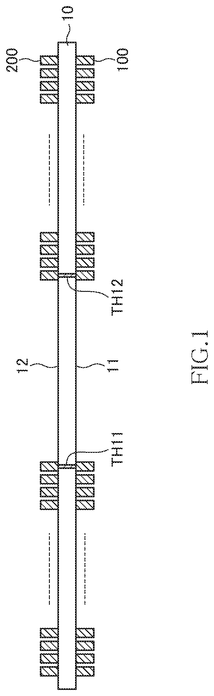
[0033]FIG. 1 is a cross-sectional view illustrating the configuration of a coil component according to the first embodiment of the present invention.

[0034]As illustrated in FIG. 1, the coil component according to the present embodiment includes an insulating substrate 10, a first coil part 100 formed on one surface 11 of the insulating substrate 10, and a second coil part 200 formed on the other surface 12 of the insulating substrate 10. Although details will be described later, the inner peripheral end of the first coil part 100 and the inner peripheral end of the second coil part 200 are connected to each other through connection conductors TH11 and TH12 penetrating the insulating substrate 10.

[0035]The material of the insulating substrate 10 can be, but not limited thereto, a transparent or translucent flexible material such as PET resin. Alternatively, the insulating substrate 10 may be a flexible substrate obtained by impregnating glass cloth with epoxy-based resin. When the in...

second embodiment

[0054]Next, a coil component according to the second embodiment will be described. The coil component according to the second embodiment differs from the coil component according to the first embodiment in that the above-described first and second coil parts 100 and 200 are replaced with first and second coil parts 300 and 400, respectively. Other basic configurations are the same as those of the coil component according to the first embodiment.

[0055]FIG. 5 is a plan view for explaining the pattern shape of the first coil part 300 as viewed from the one surface 11 side of the insulating substrate 10. FIG. 6 is a plan view for explaining the pattern shape of the second coil part 400 as viewed from the other surface 12 side of the insulating substrate 10. In the present embodiment as well, the first and second coil parts 300 and 400 have the same pattern shape.

[0056]As illustrated in FIG. 5, the first coil part 300 has six turns including turns 301 to 306, in which the turn 301 is pos...

third embodiment

[0072]Next, a coil component according to the third embodiment will be described. The coil component according to the third embodiment differs from the coil component according to the second embodiment in that the above-described first and second coil parts 300 and 400 are replaced with first and second coil parts 500 and 600, respectively. Other basic configurations are the same as those of the coil component according to the second embodiment.

[0073]FIG. 8 is a plan view for explaining the pattern shape of the first coil part 500 as viewed from the one surface 11 side of the insulating substrate 10. FIG. 9 is a plan view for explaining the pattern shape of the second coil part 600 as viewed from the the other surface 12 side of the insulating substrate 10. In the present embodiment as well, the first and second coil parts 500 and 600 have the same pattern shape.

[0074]As illustrated in FIG. 8, turns 501 to 505 constituting the first coil part 500 are each wound one round (360°). On ...


PUM

PropertyMeasurementUnit
angular distanceaaaaaaaaaa
total angular distanceaaaaaaaaaa
transparentaaaaaaaaaa

Abstract

Disclosed herein is an apparatus that includes a substrate having first and second surfaces opposite to each other, a first coil pattern formed on the first surface of the substrate, and a second coil pattern formed on the second surface of the substrate. The first coil pattern includes first and second lines, and the second coil pattern includes third and fourth lines. The first line is greater in a number of turn than the second line, and the third line is greater in a number of turn than the fourth line. The first line is connected to the fourth line, and the third line is connected to the second line.

Description

BACKGROUND OF THE INVENTIONField of the Invention[0001]The present invention relates to a coil component and, more particularly, to a coil component having a spiral-shaped planar conductor.Description of Related Art[0002]As a coil component used for various electronic devices, a coil component of a type in which a wire (coated wire) is wound around a magnetic core and, further, a coil component of a type in which a spiral-shaped planar conductor of a plurality of turns is formed on the surface of an insulating layer are known. For example, JP 2008-205215 A discloses a coil component having a configuration in which spiral-shaped coil parts are formed respectively on a plurality of insulating layers, and the inner peripheral ends thereof are connected to one another.[0003]In order to reduce DC resistance or AC resistance in a coil component constituted by a spiral-shaped planar conductor, the conductor width of the spiral-shaped planar conductor may be increased. However, simply incre...

Claims


Application Information

Patent Timeline
Patent Type & Authority Applications(United States)
IPC IPC(8): H01F27/28H01F41/04H01F27/06
CPCH01F41/041H01F27/06H01F27/2804H01F2027/2809H01F5/003
Inventor HAYAMA, JUNPEICHIYO, NORITAKAKANEKO, SHIGERUMORIKI, TOMOHIROOHISHI, TAKAHIROTOMONARI, TOSHIO
Owner TDK CORPARATION
Why Eureka
Try Eureka