
Method for maintaining cache consistency during reordering

a cache consistency and reordering technology, applied in the field of reordering, can solve the problems of reducing data transfer efficiency at the boundary of the fabric, reducing the number of physical wires between processing nodes, and adding processing units coupled to a memory that do not provide the desired level of performan

Pending Publication Date: 2020-04-09
ADVANCED MICRO DEVICES INC
View PDF7 Cites 8 Cited by
  • Summary
  • Abstract
  • Description
  • Claims
  • Application Information

AI Technical Summary

Benefits of technology

The patent text describes methods and systems for efficient data transfer in a computing system. The technical effects of the invention include improved performance and reduced latency in processing tasks, improved data transfer efficiency at the boundaries of the fabric, and improved performance in real-time applications. The invention provides a way to optimize data transfer between clients and processing nodes in a computing system, and to reduce latency and improve overall performance.

Problems solved by technology

While some processor architectures include more than one processing unit (e.g., CPU, GPU, etc.) or processing core, in some cases additional processing units coupled to a memory does not provide a desired level of performance.
However, when connecting separate dies together via the fabric, a lower number of available physical wires on the separate dies are typically used to transfer the data.
Similarly, when connecting separate processing nodes together, each with a respective fabric, a lower number of available physical wires between the processing nodes limits the bandwidth.
Consequently, data transfer efficiency is often reduced at the boundaries of the fabric in such computing systems.

Method used


Image

  • Method for maintaining cache consistency during reordering
  • Method for maintaining cache consistency during reordering
  • Method for maintaining cache consistency during reordering

Examples


case 1

[0050] Entry 20 is Selected for Issue Prior to Entry 32

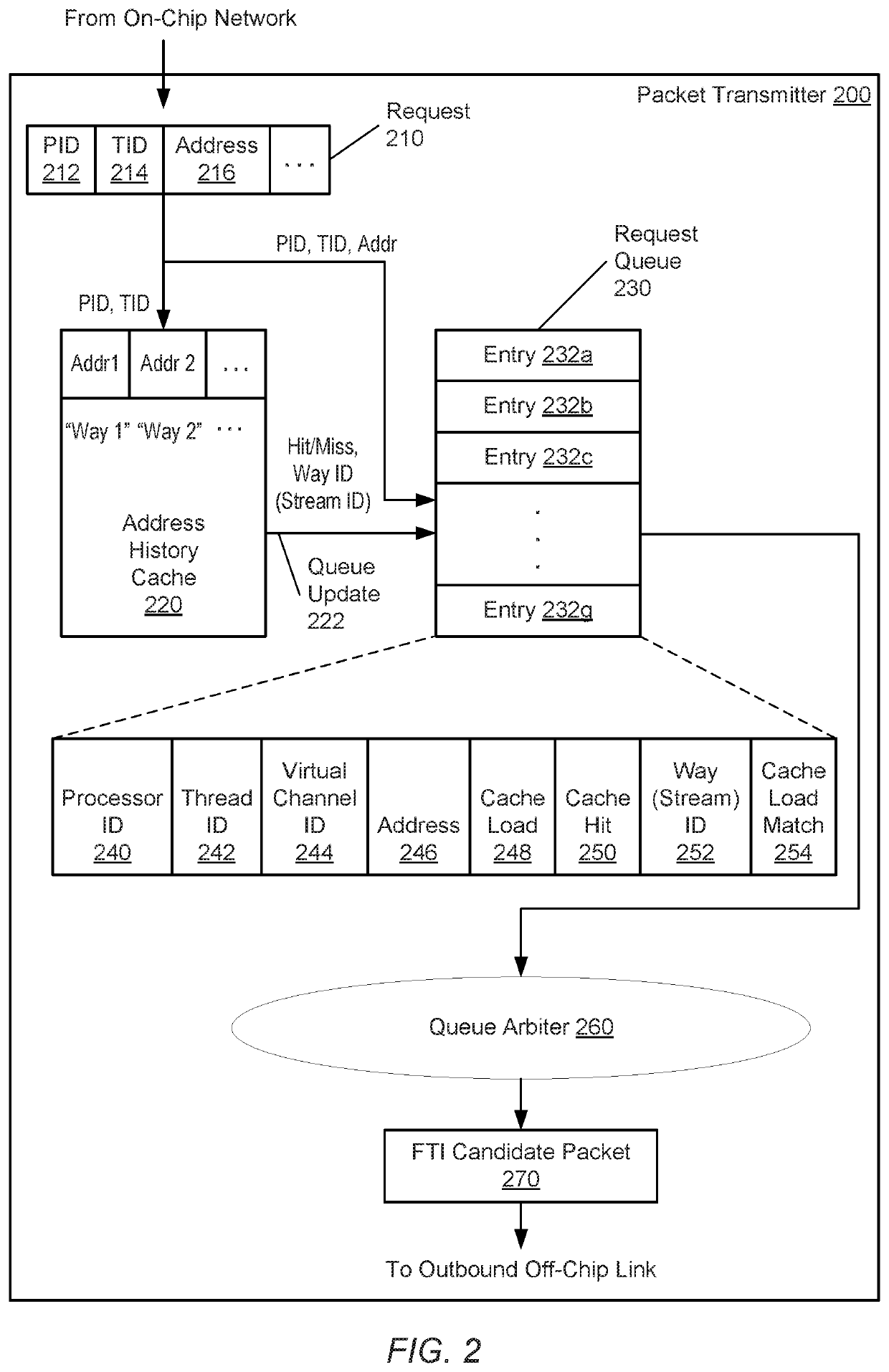
[0051]For case 1, the control logic 320 selects the younger request allocated in entry 20 for deallocation ahead of the older request allocated in entry 32. In such a case, the control logic 320 sends the resulting packet for the younger request allocated in entry 20 as an uncompressed packet, rather than an expected compressed packet. The control logic 320 sends the request address in the address field 246 (e.g., 0x100) in the uncompressed packet, since the receiver does not yet have the request address from the older request allocated in entry 32.

[0052]In the illustrated embodiment, the asserted value in the cache load match field 254 indicates that the control logic 320 should convert the selected younger request allocated in entry 20 from an expected compressed packet to an uncompressed packet. In a similar manner for requests allocated in entries 20 and 32, the requests allocated in entries 15 and 32 have case 1 occur for t...

case 2

[0053] Entry 8 is Selected for Issue Prior to Entries 15, 20, 32 and 43-44

[0054]For case 2, the control logic 320 selects the younger request allocated in entry 8 for deallocation ahead of one or more of the older requests allocated in entries 15, 20, 32 and 43-44. In such a case, the control logic 320 sends the packet generated for the younger request allocated in entry 8 as an expected uncompressed packet. As described earlier, the request allocated in entry 8 stores an asserted value in the cache load field 248. Therefore, the request generated a cache miss during a lookup of the local address history cache at the transmitter, and its respective address or portion of its address was loaded into the local address history cache. Although the control logic 320 created an expected uncompressed packet for the selected request allocated in entry 8, the control logic 320 performs an update for the one or more still-allocated older requests allocated in entries 15, 20, 32 and 43-44. The ...

case 3

[0057] Entry 32 is Selected for Issue First

[0058]For case 3, the control logic 320 selects the younger request allocated in entry 32 for deallocation ahead of one or more of the older requests allocated in entries 43-44 and ahead of one or more of the younger requests allocated in entries 7-8, 15 and 20. Case 3 is similar to case 2, but there are multiple younger requests from the same source and there is a younger request with an asserted value stored in the cache load field 248. For case 3, the control logic 320 sends the packet generated for the request allocated in entry 32 as an expected uncompressed packet. As described earlier, the request allocated in entry 32 stores an asserted value in the cache load field 248. Therefore, the request generated a cache miss during a lookup of the local address history cache at the transmitter, and its respective address or portion of its address was loaded into the local address history cache.

[0059]Although the control logic 320 created an ...


PUM


Abstract

Systems, apparatuses, and methods for performing efficient data transfer in a computing system are disclosed. A computing system includes multiple fabric interfaces in clients and a fabric. A packet transmitter in the fabric interface includes multiple queues, each for storing packets of a respective type, and a corresponding address history cache for each queue. Queue arbiters in the packet transmitter select candidate packets for issue and determine when address history caches on both sides of the link store the upper portion of the address. The packet transmitter sends a source identifier and a pointer for the request in the packet on the link, rather than the entire request address, which reduces the size of the packet. The queue arbiters support out-of-order issue from the queues. The queue arbiters detect conflicts with out-of-order issue and adjust the outbound packets and fields stored in the queue entries to avoid data corruption.

Description

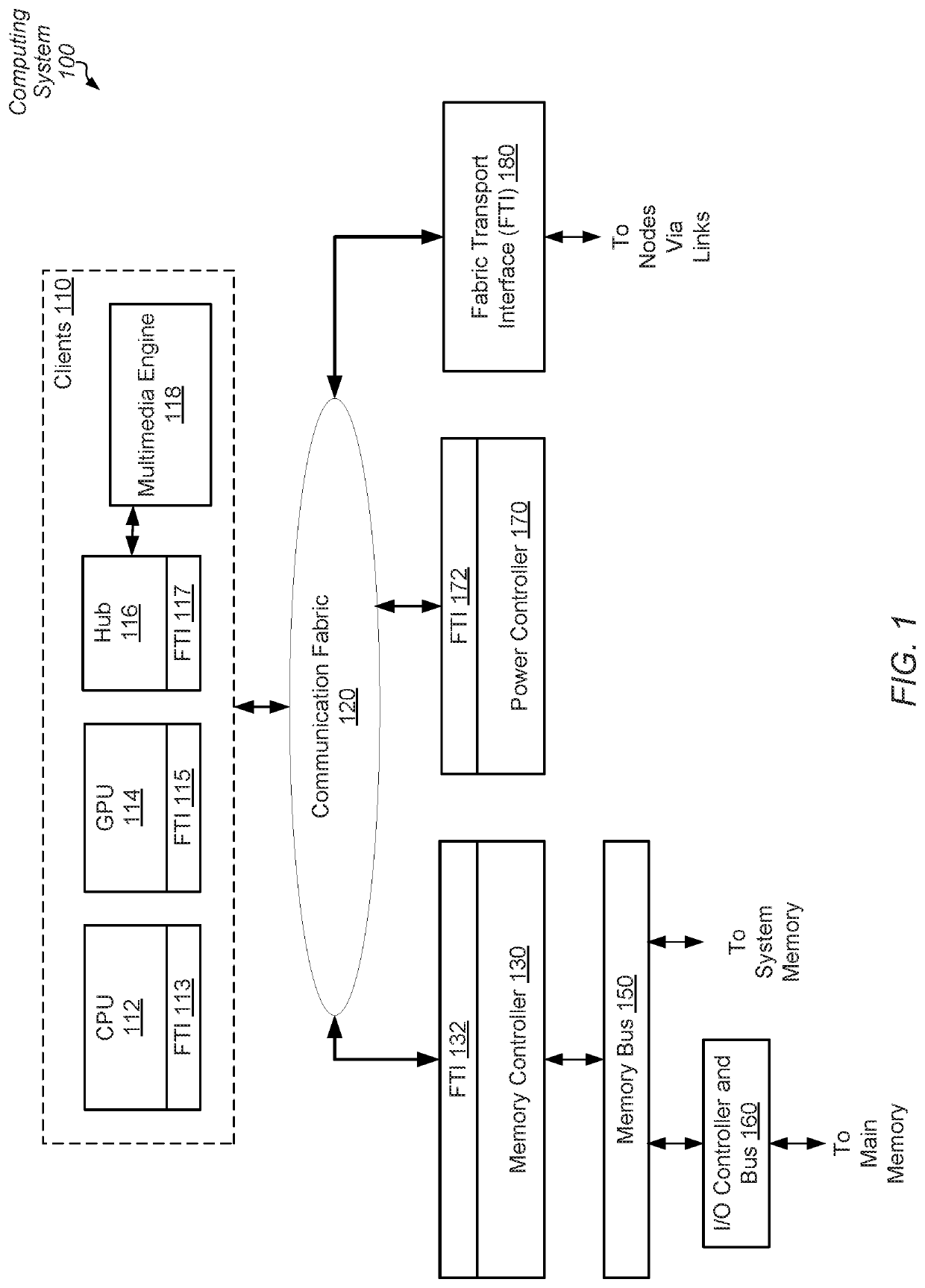
BACKGROUNDDescription of the Related Art[0001]In computing systems, some types of applications perform functions that are better able to exploit parallel processing and shared memory than other applications. Examples of such applications include machine learning applications, entertainment and real-time applications, as well as some business, scientific, medical and other applications. While some processor architectures include more than one processing unit (e.g., CPU, GPU, etc.) or processing core, in some cases additional processing units coupled to a memory does not provide a desired level of performance.[0002]Generally speaking, computing systems transfer communication messages through a communication fabric (or “fabric”). Examples of communication messages include coherency probes, interrupts, and read and write access commands and corresponding data. Examples of interconnections in the fabric are bus architectures, crossbar-based architectures, network-on-chip (NoC) communicat...

Claims


Application Information

Patent Timeline
Patent Type & Authority Applications(United States)
IPC IPC(8): H04L12/861H04L12/937H04L12/863H04L12/747H04L12/741H04L45/74
CPCH04L47/6295H04L45/742H04L45/745H04L49/254H04L49/90H04L47/624H04L47/622G06F12/1027G06F12/0864G06F2212/1024G06F2212/401G06F2212/656G06F12/1072
Inventor DONLEY, GREGGORY D.BROUSSARD, BRYAN P.
Owner ADVANCED MICRO DEVICES INC
Learn More