
Optical film

Active Publication Date: 2020-04-02
SUMITOMO CHEM CO LTD
View PDF5 Cites 0 Cited by
  • Summary
  • Abstract
  • Description
  • Claims
  • Application Information

AI Technical Summary

Benefits of technology

The patent text describes a new optical film that can be used in flexible display devices. This film provides excellent visibility in a wide angle direction, which means that it can be viewed from different angles. This technology is advantageous because it allows for more complete and complete display coverage. Overall, the invention provides an improved optical film that enhances the viewing experience of flexible display devices.

Problems solved by technology

However, according to the study of the present inventor, the conventional polyimide-based resin film may not be able to sufficiently satisfy the visibility in the wide angle direction.

Method used


Image

  • Optical film
  • Optical film
  • Optical film

Examples


production example 1

mide Resin 1

[0147]A reaction container in which a silica gel tube, a stirrer, and a thermometer were attached to a separable flask, and an oil bath were prepared. 75.6 g of 4,4′-(hexafluoroisopropylidene)diphthalic anhydride (6FDA) and 54.5 g of 2,2′-bis(trifluoromethyl)-4,4′-diaminodiphenyl (TFMB) were added to a reaction container installed in an oil bath. While the contents in the reaction container were stirred at 400 rpm, 530 g of N,N-dimethylacetamide (DMAc) was further added to the reaction container, and was kept stirred until the contents in the reaction container became a uniform solution. Subsequently, the mixture was kept stirred for an additional 20 hours while adjusting a temperature in the container to be in a range of 20 to 30° C. using the oil bath and reacted to form a polyamic acid. After 30 minutes, a stirring speed was changed to 100 rpm. After stirring for 20 hours, the reaction system temperature was returned to room temperature (25° C.), and 650 g of DMAc was...

production example 2

mide Resin 2

[0148]Polyimide resin 2 having a weight average molecular weight of 280,000 and an imidization rate of 98.3% was obtained in the same manner as in Production Example 1 except that the reaction time was changed from 20 hours to 16 hours.

production example 3

mideimide Resin 1

[0149]A reaction container in which a stirring blade is attached to a 1 L of separable flask and an oil bath were prepared. 45 g (140.52 mmol) of TFMB and 768.55 g of DMAc were added to the reaction container installed in the oil bath. The contents in the reaction container were stirred at room temperature under a nitrogen gas atmosphere and TFMB was dissolved in DMAc. Next, 18.92 g (42.58 mmol) of 6FDA was further added to the reaction container, and the contents in the reaction container were kept stirred at room temperature for 3 hours. Thereafter, 4.19 g (14.19 mmol) of 4,4′-oxybis(benzoyl chloride) (OBBC) and then 17.29 g (85.16 mmol) of terephthaloyl chloride (TPC) were further added to the reaction container and were kept stirred at room temperature for 1 hour. Next, 4.63 g (49.68 mmol) of 4-methylpyridine and 13.04 g (127.75 mmol) of acetic anhydride were further added to the reaction container, and the contents in the reaction container were stirred at room...


PUM

PropertyMeasurementUnit
Temperatureaaaaaaaaaa
Lengthaaaaaaaaaa
Fractionaaaaaaaaaa

Abstract

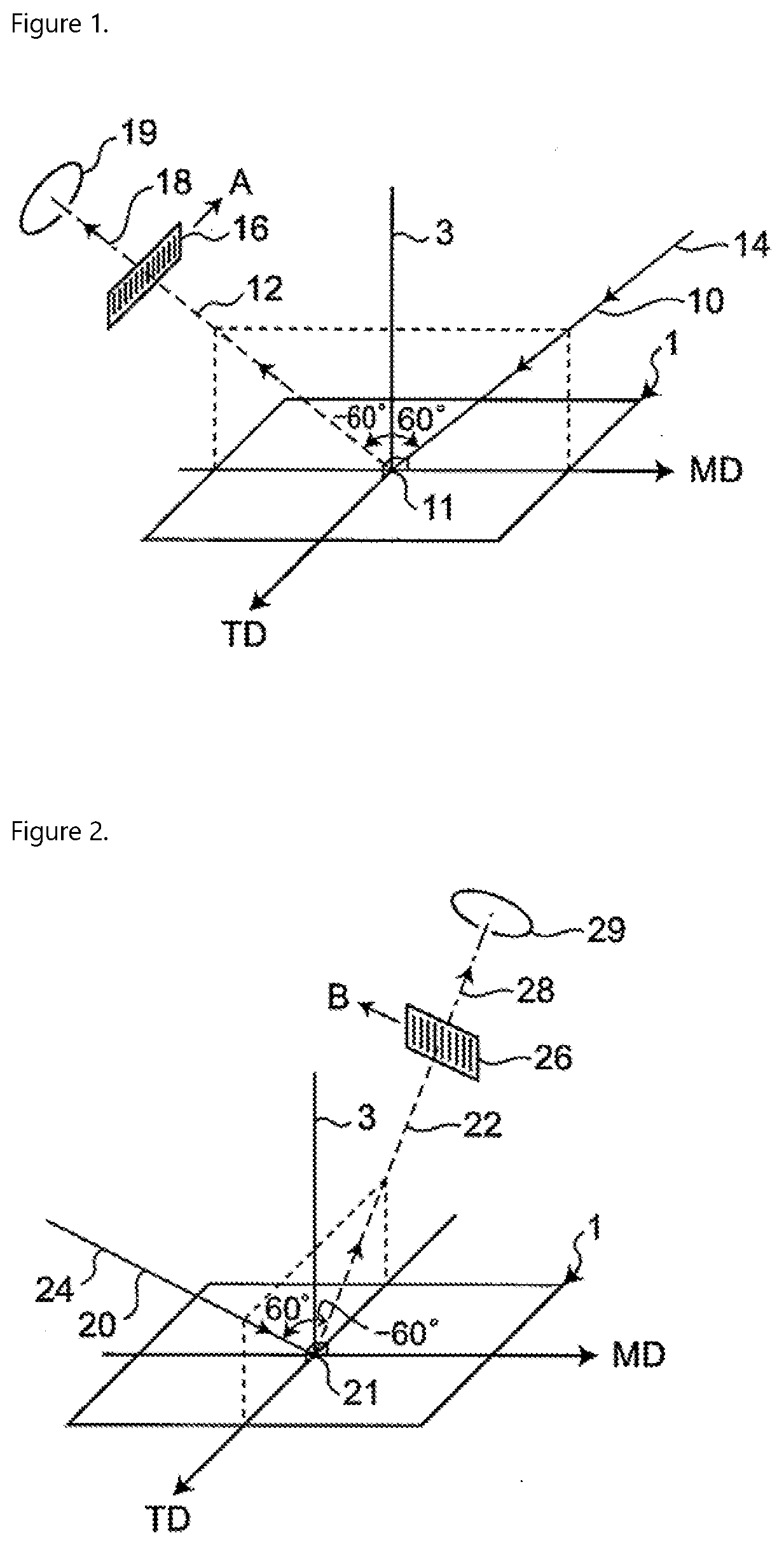
To provide an optical film having excellent visibility in a wide angle direction. An optical film including a polyimide-based resin and a polyamide-based resin and having a total light transmittance of 85% or more and a haze of 0.5% or less,in which,when a direction parallel to a machine direction in a plane of the optical film during production of the optical film is defined as an MD direction and a direction vertical to the machine direction is defined as a TD direction,for at least any one surface of the optical film, a first reflection image clarity value CMD in a direction inclined 60° in the MD direction from a vertical direction to the plane of the optical film and a second reflection image clarity value CTD in a direction inclined 60° in the TD direction from the vertical direction which are obtained when a slit width of an optical comb is 0.125 mm in accordance with JIS K 7374 satisfyFormula (1)45%≤CMD≤100%  (1),Formula (2)30%≤CTD≤100%  (2), andFormula (3)35%≤(CMD+CTD) / 2≤100%  (3).

Description

BACKGROUND OF THE INVENTIONField of the Invention[0001]The present invention relates to an optical film including at least one resin selected from the group consisting of a polyimide-based resin and a polyamide-based resin, and a flexible display device including the optical film.Description of the Related Art[0002]Conventionally, glass has been used as a material of display members such as a solar cell or an image display device. However, the glass was not sufficient to meet the recent demands for miniaturization, thinness, weight reduction, and flexibility of the display members. Therefore, as an alternative material of glass, various films are being considered. Examples of such a film include a polyimide film (for example, JP-A-2009-215412).SUMMARY OF THE INVENTION[0003]When the polyimide film is applied to transparent members such as a front plate of a flexible display device, an image may be displayed with an image display surface being bent, and thus, excellent visibility in a...

Claims


Application Information

Patent Timeline
IPC IPC(8): G02B1/14G06F3/044C08G73/10C08G73/14C09D133/14
CPCC08G73/14G06F3/0443C08G73/1067G06F2203/04102G02B1/14G06F2203/04111C09D133/14G02B5/30G09F9/301G02F1/13338C08G73/1039C09D179/08C08J2367/02C08J2475/14C08J2479/08C08L79/08C08L2205/025C08L2203/16G02B5/3016G02B5/3033B32B7/023B32B27/08B32B27/281B32B27/34B32B27/20C08J5/18G06F3/041G02F1/1335B32B2307/51
Inventor DAIMATSU, KAZUKIFUKUI, HITOSHIKARASAWA, MASAYOSHI
Owner SUMITOMO CHEM CO LTD
Learn More