Pedal apparatus

a pedal device and pedal technology, applied in the direction of mechanical control devices, process and machine control, instruments, etc., can solve the problems of unsuitable devices for prolonged driving, driver's right foot weight falling on the pedal device, and unintentionally performing brake operation, etc., to prevent the increase of load, reduce fatigue from prolonged driving and/or psychological discomfort, and achieve the effect of less cos

Inactive Publication Date: 2020-04-02
TSUNEMI KAZUO
View PDF0 Cites 2 Cited by
  • Summary
  • Abstract
  • Description
  • Claims
  • Application Information

AI Technical Summary

Benefits of technology

[0024](1) Since the pedal device may be attached to an existing brake pedal without remodeling it, the pedal device may be implemented more inexpensively; (2) Since the distance to the stepping surface does not change, the driver's knee position is also unchanged, preventing the increase of the load to the driver's overall leg / foot compared to the prior art; (3) The brake and the accelerator may be operated with the driver's right heel in contact with the floor; Also, unlike in the prior art, the driver can maintain the conventional natural driving posture without placing his / her right foot towards the center of vehicle, thus fatigue from prolonged driving and / or psychological discomfort may be reduced; Moreover, upon left turns, etc., the right foot may also be used to maintain the driver's posture, thus improving the stability of driving posture; (4) By providing angles in the up-down and front-back directions of the base, respectively, biasing force is enhanced toward the direction to close the accelerator upon braking, thereby ensuring the braking; Also, since the accelerator pad and the bracket are integrally attached to the existing brake pedal, the stepping surface of the brake pedal is practically enlarged, thus, further ensuring the braking by allowing the driver to step on anywhere on the brake pedal for braking; and (5) Since the external shape of the pedal device has a compact and simple structure consisting of the frame and the accelerator pad only without exposing any of its device elements outside this external shape, there is little risk of interference with the internal structure of the vehicle, foreign matter getting trapped, or malfunction and / or failure.

Problems solved by technology

However, in Prior Art 1, due to its configuration where its pedal device is attached directly above an existing brake pedal, the device (specifically, the pedal stepping surface) inevitability projects toward the driver's side, elevating the driver's knee position and producing space between the driver's seating surface and the lower side of the driver's thigh, to cause a persistent tendency that the driver's right foot weight falls on the pedal device.
Accordingly, this device is unsuited to a prolonged drive due to the increased load to the driver's pedaling foot and / or leg in addition to the possibility that the driver may unintentionally performs the braking operation.
Certainly, it is possible to modify the brake mechanism by removing not only the accelerator pedal, but also the existing brake pedal so that the pedal device will not project toward the driver's side, but such a modification may increase the device cost as well as causing a violation of law regarding modifications of important safety parts.
On the other hand, Prior Art 2 not only has a similar problem, but also has another problem in its inventive configuration itself that it is operated by mounting the entire foot sole on a rotatable accelerator pedal.
For example, when the driver receives a rightward G in a left-hand curve with his / her heel touching the floor, the driver can operate the accelerator by simply using the ankle while holding down the right foot firmly, but in the configuration of Prior Art 2, if the driver applies force in his / her right foot, she / he may unconsciously operate the brake while operating the accelerator, causing a danger.
Moreover, the prior art have no choice but to have a complex and bulky mechanism.
In the configuration of Prior Art 1, since a complex accelerator mechanism consisting of an accelerator wire arm, an accelerator lever, an accelerator pad, etc. exists to the right of the brake pedal, if the foot pressing down on the brake pedal slightly shifts rightward during an emergency full braking to step on the accelerator mechanism by mistake, enough braking may not be achieved, leading to a device failure.
The large pedal not only tightens the space around the driver's feet to inconvenience the driver when getting in and out of the vehicle, but also compromises the pedal operability and / or operational experience due to the increased inertial weight as well as increasing the risk of hindering the braking operation when some article is dropped on the floor and stuck beneath the pedal.

Method used


Image

  • Pedal apparatus
  • Pedal apparatus
  • Pedal apparatus

Examples


Embodiment Construction

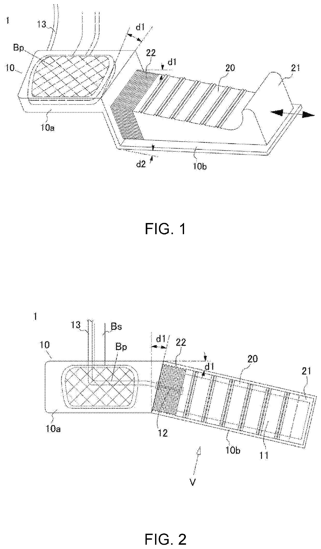
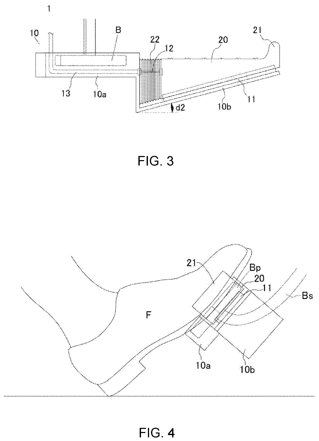
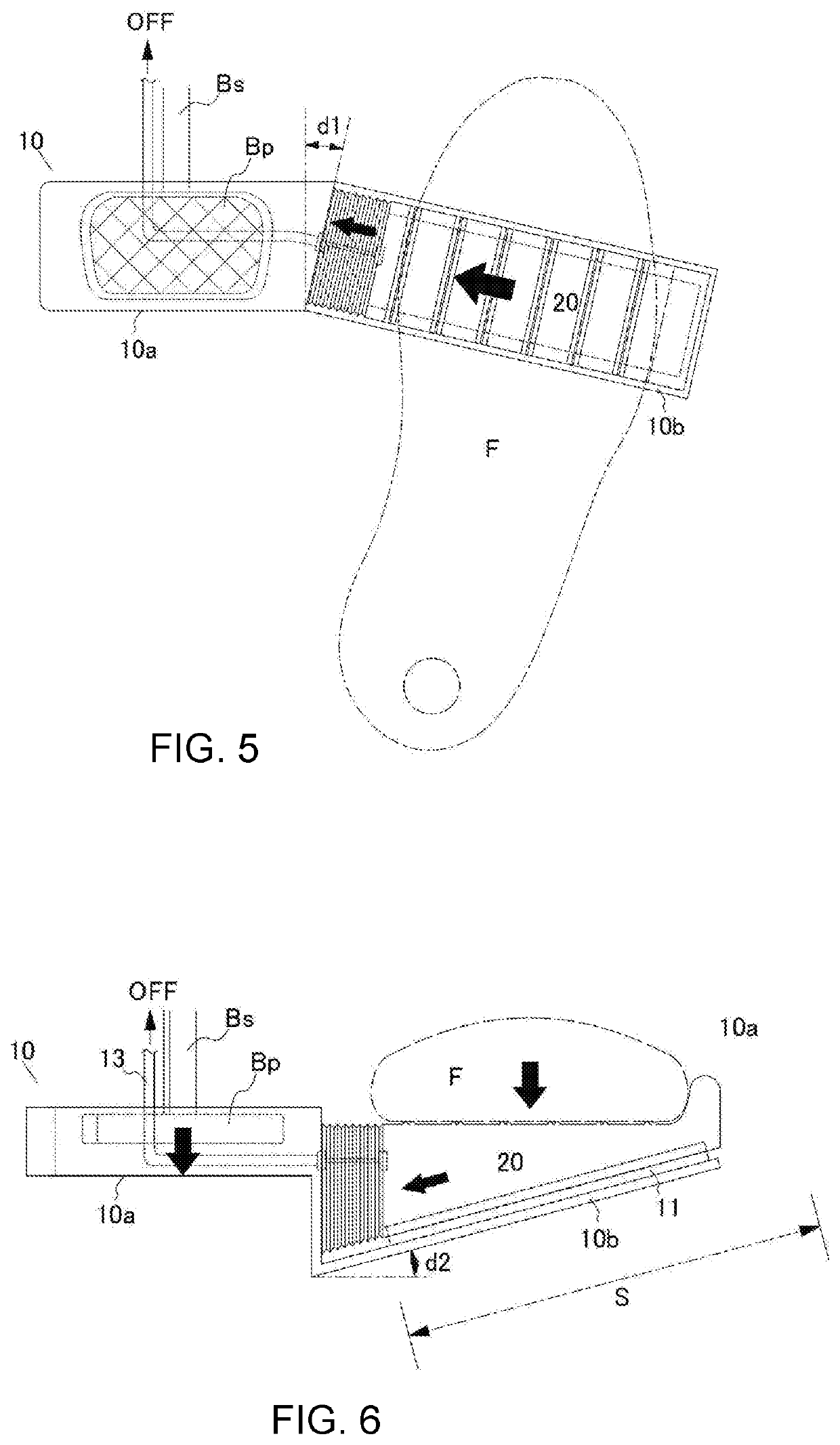
[0033]One embodiment of the present invention will be described below based on drawings. FIG. 1 is a perspective view showing an embodiment of a pedal device according to the present invention; FIG. 2 is a plan view of the pedal device; and FIG. 3 is a front view of the pedal device viewed from the direction of an arrow V in FIG. 2. FIG. 4 is a side view of the pedal device in use, attached to a existing brake pedal B, seen from the right side of the pedal device. Also, FIG. 5 to FIG. 8 are diagrams showing operations and actions of the pedal device 1: wherein FIG. 5 is a plan view during acceleration (the accelerator is open); FIG. 6 is a front view during acceleration; FIG. 7 is a plan view in braking (the accelerator is closed); and FIG. 8 is a front view during braking.

[0034]The pedal device 1 consists of a frame 10 with a configuration having a generally box-shaped bracket 10a and a base 10b, which is a rectangular plate material, wherein the bracket 10a is attachable to the br...


PUM


Abstract

There is provided an inexpensive pedal device in a compact and simple configuration of the one-pedal scheme, wherein the pedal device may be attached to an existing brake pedal without remodeling the brake pedal, wherein the pedal device does not cause the pedal stepping surface to project toward a driver, wherein an accelerator and a brake are operable with the driver's right heel in contact with the floor, wherein upon braking the pedal device always operates toward a direction to close the accelerator, and wherein the pedal device allows some deviation of a pedal-stepping position. A pedal device, comprising: a frame consisting of a bracket attachable to an existing brake pedal, and a base projecting rightward from the bracket; an accelerator pad attached to an upper surface of the base so that the accelerator pad is smoothly slidable rightward and leftward through a slide mechanism provided on the upper surface of the base; and a transmission unit for transmitting a position of the accelerator pad to an accelerator device of a vehicle, wherein the base is sloped downward toward the bracket, wherein the accelerator pad is shaped so that its stepping surface is not higher than a stepping surface of the brake pedal when the accelerator pad is at its leftmost position, wherein the accelerator pad comprises a biasing unit for biasing the accelerator pad leftward, and wherein the base is provided on the bracket at an angle so that the right end of the base is closer to a driver.

Description

FIELD OF THE INVENTION[0001]The present invention relates to a pedal device of so-called “one-pedal” scheme, which pedal device integrally equipped with a brake operation mechanism and an accelerator operation mechanism for an automobile; and more specifically, the present invention relates to a pedal device enabling brake and accelerator operations with a single pedal by removing an existing accelerator pedal (i.e., gas pedal) and subsequently attaching the accelerator pedal to an existing brake pedal to connect the brake pedal to the accelerator operation mechanism.BACKGROUND OF THE INVENTION[0002]Pedal devices of so-called “one-pedal” scheme are known to have a brake pedal for being pressed on in a forward direction by a driver's foot and an accelerator operation mechanism integrally provided on the brake pedal, wherein the accelerator operation mechanism may be operated in a right or left direction by the front part of the driver's foot. With such a configuration, the driver no ...

Claims


Application Information

Patent Timeline
Patent Type & Authority Applications(United States)
IPC IPC(8): B60K26/02G05G1/36G05G1/38G05G1/42B60T7/06
CPCG05G1/305G05G1/42G05G1/36B60T7/06B60K26/02G05G1/38B60T7/02B60T7/04G05G1/01G05G1/44B60Y2302/09G05G1/30G05G1/487
Inventor TSUNEMI, KAZUO
Owner TSUNEMI KAZUO
Why Eureka
Try Eureka