
Multiphase pump

a multi-phase pump and pump body technology, applied in the direction of machines/engines, liquid fuel engines, borehole/well accessories, etc., can solve the problems of not being able to provide a buffer tank, affecting the reliability of the pump, and reducing the efficiency of the pump, so as to minimize the amount of equipment involved, optimize the reliability of the pump, and optimize the effect of exploitation

Pending Publication Date: 2020-03-19
SULZER MANAGEMENT AG
View PDF1 Cites 3 Cited by
  • Summary
  • Abstract
  • Description
  • Claims
  • Application Information

AI Technical Summary

Benefits of technology

The invention is a multiphase pump with a short length return line that prevents separation effects and slugging in the process fluid. The pump creates a very homogeneous mixture of the process fluid, with a high concentration of gas in the liquid phase. The homogenized fluid enters the return line directly from the discharge annulus, eliminating the need for additional piping and minimizing pressure drop and thermal variance to prevent hydrate formation. The short length of the return line reduces separation effects and enables optimal pump operation.

Problems solved by technology

Needless to say that the design of such pumps is challenging, in particular because these pumps shall operate in a difficult subsea environment for a long time period with as little as possible maintenance and service work.
One of the challenges regarding the design of multiphase pumps is the fact that in many applications the composition of the multiphase process fluid is strongly varying during operation of the pump.
These variations may occur very sudden and could cause a drop in pump efficiency, vibrations of the pump or other problems.
However, in some applications it might not be reasonable to provide a buffer tank, e.g. due to technical reasons or due to a lack of available space.
But even when using a buffer tank, the variations in the composition of the multiphase process fluid can still be strong so that it cannot be ensured that the multiphase pump is always operating within the operating range which the pump is designed.
In particular in the situation of a very high GVF there is a risk that the liquid flow through the pump falls below the minimum flow, at which the pump is operating in a safe, reliable and efficient manner.
Thus, depending on the actual conditions it might be that the liquid flow through the return line is too low to ensure reliable operation of the pump.
However there is the problem that the liquid extraction unit is not really capable of handling the wide range of operational points, e.g. the strong variations in the GVF.
Therefore the solution with the liquid extraction unit is not really satisfying in praxis.
This causes adverse effects in the process fluid to be recycled, such as phase separation, stratification or slug generation.
In addition, the short length cause only very low pressure losses along the return line resulting from friction losses in the return line.

Method used


Image

  • Multiphase pump
  • Multiphase pump
  • Multiphase pump

Examples


first embodiment

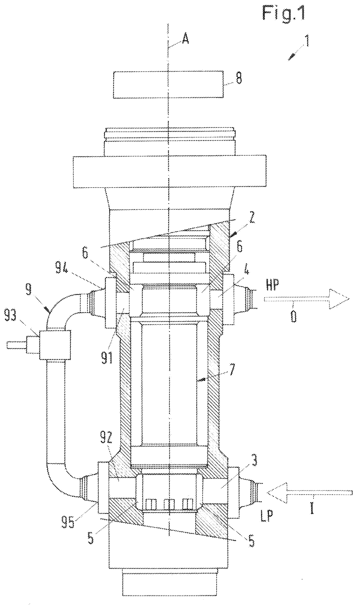
[0059]The return line 9 is designed as a pipe connecting the discharge annulus 6 with the inlet annulus 5. In the first embodiment shown in FIG. 1 the return line 9 is designed as an external pipe and arranged at the outside of the housing 2. The return line 9 is fixed to the housing 2 by means of a first flange connection 94 connecting the inlet 91 of the return line 9 with the discharge annulus 6, and by means of a second flange connection 95 connecting the outlet 92 of the return line 9 with the inlet annulus 5.

[0060]The return line 9 is designed as a pipe having the shortest length that is possible or technically reasonable when considering constructional or structural aspects. Ideally, the length of the pipe constituting the return line is essentially the same as the distance between the discharge annulus 6 and the inlet annulus 5. In practice, the return line 9 is somewhat longer than the distance between the discharge annulus 6 and the inlet annulus 5 due to constructional re...

third embodiment

[0076] the return line 9 is fixedly connected to the housing 2 in a non-detachable manner. The return line 9 is for example welded to the housing 2 as indicated by the welding seams 96 in FIG. 3.

[0077]FIG. 4 shows a cross-sectional view of a fourth embodiment of a multiphase pump 1 according to the invention. The fourth embodiment is here designed as a vertical pump. The drive unit 8 for rotating the pump rotor 7 is not shown in FIG. 4.

fourth embodiment

[0078]In the fourth embodiment the return line 9 is an internal line, i.e. the return line 9 is arranged inside the housing 2 of the multiphase pump 1.


PUM


Abstract

A multiphase pump includes a housing having a pump inlet and a pump outlet for a process fluid, an inlet annulus configured to receive the process fluid from the pump inlet, a discharge annulus configured to discharge the process fluid into the pump outlet, a pump rotor configured to rotate about an axial direction and arranged within the housing, the pump rotor being configured to convey the process fluid from the inlet annulus to the outlet annulus, and a return line configured to return the process fluid from the high pressure side to the low pressure side, the return line including an inlet configured to receive the process fluid, an outlet configured to discharge the process fluid and a control valve configured to open and close the return line, the inlet of the return line arranged directly at the discharge annulus.

Description

CROSS-REFERENCE TO RELATED APPLICATION[0001]This application claims priority to European Patent Application No. 18194754.0, filed Sep. 17, 2018, the content of which is hereby incorporated herein by reference.BACKGROUNDField of the Invention[0002]The invention relates to a multiphase pump for conveying a multiphase process fluid.Background of the Invention[0003]Multiphase pumps are used in many different industries, where it is necessary to convey a process fluid which comprises a mixture of a plurality of phases, for example a liquid phase and a gaseous phase. An important example is the oil and gas processing industry where multiphase pumps are used for conveying hydrocarbon fluids, for example for extracting the crude oil from the oil field or for transportation of the oil / gas through pipelines or within refineries.SUMMARY[0004]In view of an efficient exploitation of oil- and gas fields there is nowadays an increasing demand for pumps that may be installed and operated directly o...

Claims


Application Information

Patent Timeline
IPC IPC(8): F04D3/00F04D29/18F04D29/52
CPCF04D29/522F04D3/005F04D29/181F04D31/00F04D29/40F04D1/06F04D15/0005F04D15/0011F04D13/086F04C13/001F04C15/06F04C13/008F04C15/0057E21B43/12F04C2210/24F05B2210/13F04D9/005
Inventor BOURNE, MATTHEW
Owner SULZER MANAGEMENT AG
Learn More