Lubricant change system for power transmissin equipment

a technology of power transmissin and lubricant change, which is applied in the direction of machines/engines, liquid transfer devices, turbines, etc., can solve the problems of inconvenient routine maintenance, inconvenient access, and high cost, and achieve the effect of increasing safety

Pending Publication Date: 2020-03-19
HORN JAMES DAWSON +1
View PDF4 Cites 1 Cited by
  • Summary
  • Abstract
  • Description
  • Claims
  • Application Information

AI Technical Summary

Benefits of technology

The present invention provides a mobile vehicle lubrication unit that can be located close to equipment to be lubricated and have the lubricating oil changed and / or filtered. This results in a safer system for changing oil in difficult to access equipment such as overhead gearboxes used on conveying equipment installed at higher elevations than can be reached safely on the ground. The oil change trailer includes a waste oil sampling valve and filters to protect the oil transfer pumps and a new oil transfer pump with an output meter for transferring a selected amount of new oil to the gearbox. Additionally, the system can fill the grease system of the conveyor. Overall, the invention increases safety and minimalizes climbing to the top of the conveyor to change the gear box oil.

Problems solved by technology

Routine maintenance is inconvenient and access is limited due to the height of the unit or construction and operational environment of the equipment.
Ladders or personnel lifts might be used but such work is still relatively unsafe, inconvenient, expensive, and often requires downtime for the unit and support equipment.
Any one of these tasks may require unnecessary risk when accomplished from a ladder or even a lift.
This poses a problem for the operator and it is often difficult to position lifting equipment for changing the oil, manpulating hoses, and / or removal and storage of contaminated fluid due to the size of conveying systems and close proximity of support equipment.
These pose potential safety issues to the operator when draining and filling the gearbox.

Method used


Image

  • Lubricant change system for power transmissin equipment
  • Lubricant change system for power transmissin equipment
  • Lubricant change system for power transmissin equipment

Examples


Embodiment Construction

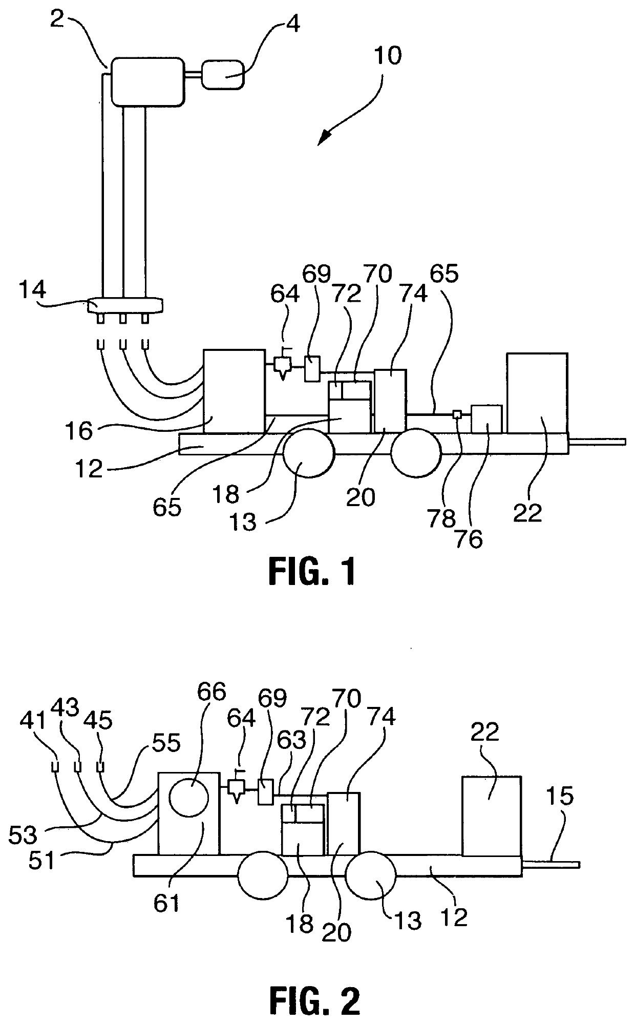
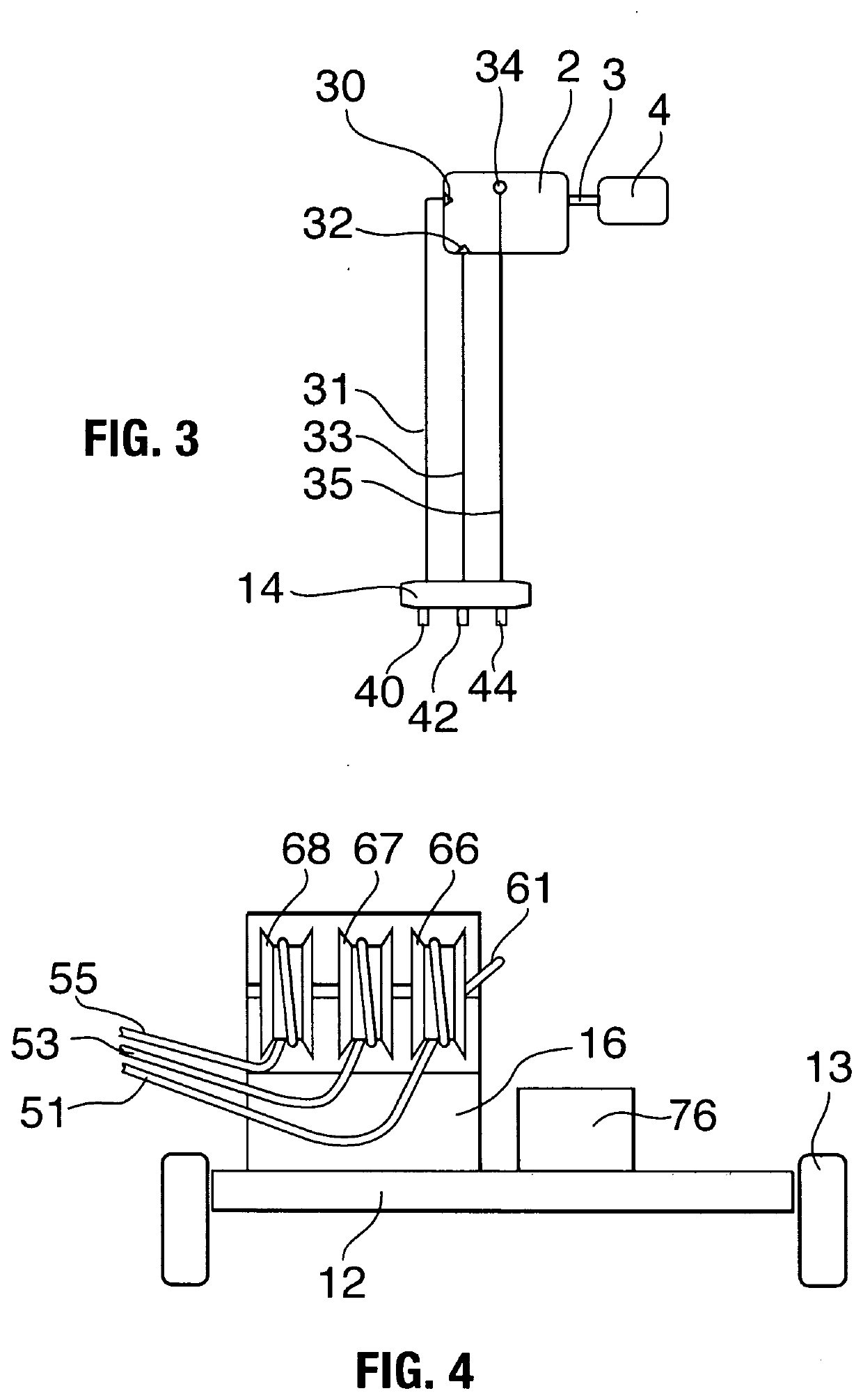
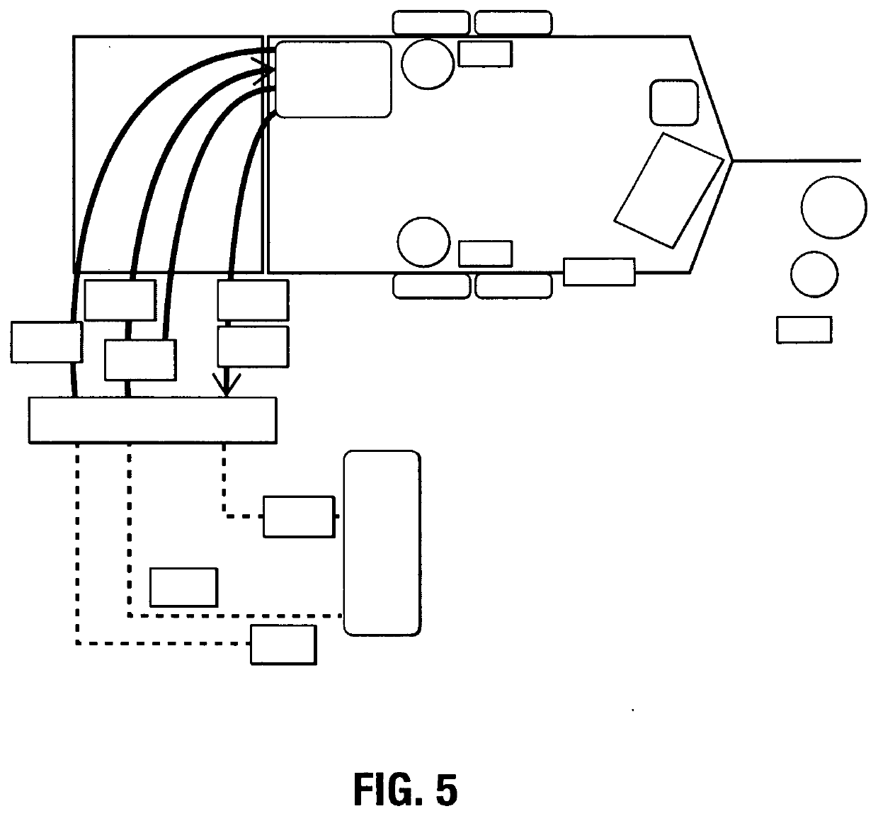
[0042]In accordance with the present invention, there is provided an overhead gearbox oil change system 10 which can be mounted to a vehicle such as a truck or trainer. The system includes piping connecting the gearbox 2 to a manifold 14 located at a convenient location for the user and an oil change trailer 12 with hose reels for connecting a fresh oil container 18 and pump 70 and a waste oil container 20 and pump 74 to the manifold connections, along with a 110 VAC generator 22 to power the pumps and for other needs.

[0043]The gearbox 2 is driven by a motor 4 connected by a shaft 3. The gearbox is used to drive some device like a conveyor, crushing or grinding equipment, fans or the like. The gearbox 2 includes a drain hole 32, a fill hole 30 and an air vent hole 34. A pipe 31 connects the fill hole 30 to a male quick disconnect coupling 40 mounted on a manifold 14. The manifold 14 is located at a convenient height of about five feet above the ground level where a user may park an ...


PUM


Abstract

A mobile vehicle lubrication unit for serving power transmission equipment elevated above ground level such as conveyors whereby the lubricant containing gear reducer unit is disposed in an enclosed body mounted on an upper portion of an elevated conveyor. The system includes a manifold system connectable to trailer mounted storage tanks for lubricants, pumps, filters, air supplies and supply lines, and transfer means mounted on a truck or trailer including side access to the control panel and transfer hoses enabling the user to transfer lubricants to elevated equipment such as conveyors by pulling along side of same. The device changes, filters, and replaces the oil in a reducer gearbox or other lubricant containing equipment which is not easily accessed from the ground level. Air presssure is used to evaculate used oil from the conveyor gear motor and / or reducer units and replaces the used oil with filtered or new oil through oil lines and hoses with quick disconnects which may be positioned on a manifold at ground level having oil lines in fluid communication with the gear motor / reducer unit.

Description

TECHNICAL FIELD[0001]The present invention relates to the field of apparatus used to check, replace, and / or filter lubricating oil in a gearbox, reducer, or other mechanical device having an oil reservoir positioned in a remote location.BACKGROUND OF THE INVENTION[0002]Industries involving rock quarries, mining, and the like use elevated conveyors, crushing or grinding equipment, pumps or any elevated equipment using gear reducers or gearboxes driven by electric motors. These gearboxes and drive motors are typically located overhead at the top end of the conveyor. Routine maintenance is inconvenient and access is limited due to the height of the unit or construction and operational environment of the equipment. Ladders or personnel lifts might be used but such work is still relatively unsafe, inconvenient, expensive, and often requires downtime for the unit and support equipment. An operator or maintenance worker must somehow get lifted into position, remove guarding and set it asid...

Claims


Application Information

Patent Timeline
IPC IPC(8): F01M11/02F01M1/02F01M1/10
CPCF01M2011/021F01M2011/035F01M11/02F01M2001/0284F01M1/02F01M2011/068F01M1/10F16N2210/02F16N2210/08F16N39/06F01M11/04B67D7/845F16N31/006F16N31/00
Inventor HORN, JAMES DAWSONKOPPELMAN, WILLIAM
Owner HORN JAMES DAWSON
Why Eureka
Try Eureka