Eureka AIR delivers breakthrough ideas for toughest innovation challenges, trusted by R&D personnel around the world.

In-cell liquid crystal panel and liquid crystal display device

a liquid crystal panel and liquid crystal display technology, applied in the field of in-cell liquid crystal panels, can solve the problems of reducing the sensitivity of the touch panel, unstable capacitance of the sensor electrode, etc., and achieves the effects of reducing surface resistance, good anti-static function, and suppressing the generation of electrostatic unevenness

Active Publication Date: 2020-01-30
NITTO DENKO CORP
View PDF2 Cites 5 Cited by
  • Summary
  • Abstract
  • Description
  • Claims
  • Application Information

AI Technical Summary

Benefits of technology

The present invention provides a pressure-sensitive adhesive layer attached polarizing film for in-cell type liquid crystal panels with antistatic function. This film can effectively secure a sufficient contact area with the conduction structure on the side surface of the panel, preventing electrostatic unevenness and ensuring conduction reliability in a humidified environment. The surface resistance value of at least one layer in the film can be controlled within a predetermined range, providing a good antistatic function without reducing touch sensor sensitivity or durability under humidified environment.

Problems solved by technology

The static electricity generated in this way affects the alignment of the liquid crystal layer inside the liquid crystal display device and causes defects.
In the case where a conductive layer such as an antistatic layer is provided between the transparent electrode pattern and the user's finger, the electric field between a driving electrode and a sensor electrode is disturbed, the sensor electrode capacitance becomes unstable and the touch panel sensitivity decreases, causing malfunction.

Method used


Image

  • In-cell liquid crystal panel and liquid crystal display device
  • In-cell liquid crystal panel and liquid crystal display device
  • In-cell liquid crystal panel and liquid crystal display device

Examples


examples

[0112]Although the present invention will be described in detail below based on Production Examples and Examples, it should be understood that the present invention is not limited to such Examples. The parts and percentages in each Example are on a weight basis. Room temperature standing conditions not specified below are all 23° C. and 65% RH.

[0113]The weight average molecular weight (Mw) of the (meth)acrylic polymer was measured by GPC (gel permeation chromatography). The ratio Mw / Mn was also measured in the same manner.[0114]Analyzer: HLC-8120 GPC, manufactured by Tosoh Corporation[0115]Column: G7000HXL+GMHXL+GMHXL, manufactured by Tosoh Corporation[0116]Column size: 7.8 mmφ×30 cm each in total 90 cm[0117]Column temperature: 40° C.[0118]Flow rate: 0.8 mL / min[0119]Injection volume: 100 μL[0120]Eluent: Tetrahydrofuran[0121]Detector: Differential refractometer (RI)[0122]Standard sample: Polystyrene

(Preparation of Polarizing Film)

[0123]An 80 μm-thick polyvinyl alcohol film was stretc...


PUM

PropertyMeasurementUnit
thicknessaaaaaaaaaa
thicknessaaaaaaaaaa
thicknessaaaaaaaaaa

Abstract

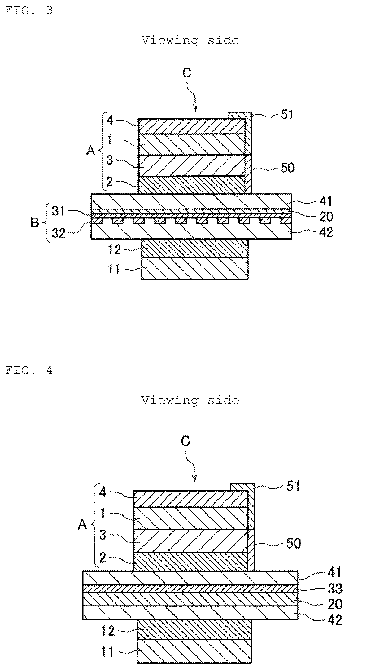
An in-cell type liquid crystal panel is disclosed including an in-cell type liquid crystal cell provided with a liquid crystal layer, a first transparent substrate and a second transparent substrate sandwiching the liquid crystal layer, and a touch sensing electrode unit related to a touch sensor and a touch-driven function between the first transparent substrate and the second transparent substrate and a pressure-sensitive adhesive layer attached polarizing film disposed, via a first adhesive layer and without interposing a conductive layer, to the first transparent substrate side on a viewing side of the in-cell type liquid crystal cell. The pressure-sensitive adhesive layer attached polarizing film comprises a surface treatment layer, a first polarizing film, and a first pressure-sensitive adhesive layer in this order, or comprises the surface treatment layer, the first polarizing film, an anchor layer, and the first pressure-sensitive adhesive layer in this order.

Description

TECHNICAL FIELD[0001]The present invention relates to an in-cell type liquid crystal cell in which a touch sensing function is incorporated, and an in-cell type liquid crystal panel comprising a pressure-sensitive adhesive layer attached polarizing film on the viewing side of the in-cell type liquid crystal cell. Further, the present invention relates to a liquid crystal display device using the liquid crystal panel. The liquid crystal display device with a touch sensing function using the in-cell type liquid crystal panel of the present invention can be used as various input display devices for mobile devices and the like.BACKGROUND ART[0002]Generally, in liquid crystal display devices, polarizing films are bonded to both sides of a liquid crystal cell with a pressure-sensitive adhesive layer interposed therebetween from the viewpoint of image forming system. In addition, ones that mount a touch panel on a display screen of a liquid crystal display device have been put to practical...

Claims


Application Information

Patent Timeline
Patent Type & Authority Applications(United States)
IPC IPC(8): G02F1/1335G06F3/041G06F3/044C09J133/08
CPCG06F3/044G02F2202/28G02F2202/22G02F1/133528G02F2001/133562G02F1/13338G06F3/0412C09J133/08G02B1/14G02B1/16G02B5/30G09F9/30C09J139/08C09J133/06G06F2203/04103G02B5/3033G02F1/133562
Inventor FUJITA, MASAKUNIYAMAMOTO, SATOSHITOYAMA, YUSUKE
Owner NITTO DENKO CORP
Why Eureka
Eureka Blog
Learn More